Semiconductor ceramic protection equipment

A technology for protecting equipment and semiconductors. It is applied in metal processing equipment, grinding/polishing equipment, grinding machines, etc. It can solve the problems of low surface smoothness of semiconductor ceramics, heat generation, and the decline in the protection effect of semiconductor ceramics, so as to avoid heat generation and adsorption of dust. Avoid the effect of polishing dead corners

Inactive Publication Date: 2021-03-30
李三源
View PDF5 Cites 4 Cited by
  • Summary
  • Abstract
  • Description
  • Claims
  • Application Information

AI Technical Summary

Problems solved by technology

[0004] Aiming at the deficiencies in the prior art, the purpose of the present invention is to provide a semiconductor ceramic protection device to solve the problem of the prior art. The current semiconductor ceramic protection device refers to the polishing equipment before the semiconductor ceramics leaves the factory. The burrs are removed to make the ceramic surface smooth and protect the ceramic body. Since the ceramic powder will fall during the deburring and grinding process, the grinding disc will generate static electricity due to high-speed rotating friction, and the falling powder will be easily adsorbed on the surface of the grinding disc. Continue to polish the surface of semiconducting ceramics, resulting in low smoothness of the processed semiconducting ceramics surface, which in turn leads to a decrease in the protective effect of semiconducting ceramics

Method used


Image

  • Semiconductor ceramic protection equipment
  • Semiconductor ceramic protection equipment
  • Semiconductor ceramic protection equipment

Examples


Embodiment 1

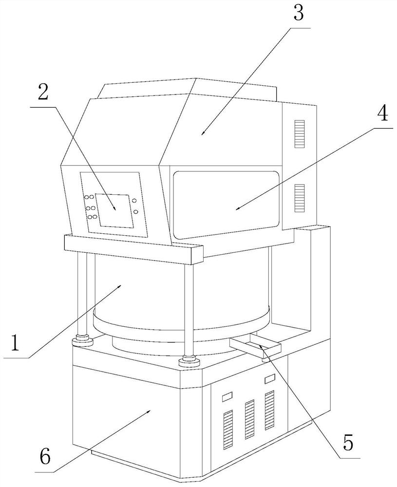
[0026] as attached figure 1 to attach Figure 5 Shown:

[0027] Its structure includes a machining center 1, a controller 2, a driving box 3, an observation window 4, an end slot 5, and an equipment box 6. The upper end of the machining center 1 is movably matched with the driving box 3, and the upper end of the driving box 3 is in cooperation with the controller. 2. Embedded connection, the observation window 4 is fixed to the left and right ends of the drive box 3 with bolts, the lower end of the machining center 1 is in clearance with the upper end of the equipment box 6, and the end row groove 5 is nested and connected to the right end of the machining center 1. The exhaust end groove 5 is welded to the upper end of the equipment box 6. The machining center 1 includes a polisher 11, a protective cover 12, a rotating sleeve 13, a construction warehouse 14, and a fixed seat 15. The polisher 11 and the rotating sleeve 13 The overall nesting fit, the bottom of the rotating s...

Embodiment 2

[0034] as attached Figure 6 to attach Figure 7 Shown:

[0035] Wherein, the loose powder tank a4 includes a drainage bar b1, a swing frame b2, a discharge tank b3, a diverter block b4, and a clamping plate b5. The drainage bar b1 is hingedly connected to the surface of the discharge tank b3. The two sides are movable and fit, the swing frame b2 is interference fit with the inner wall of the clamp b5, the two sides of the diverter block b4 are in clearance fit with the swing frame b2, and the discharge groove b3 is fixed on the inner side of the clamp b5 to cooperate with it. The drainage bar b1 is in the shape of a long wavy strip as a whole. There are two groups, one group of three, and they are distributed on the top of the discharge groove b3 for swing hinged connection. Among them, the swing frame b2 is conducive to swinging to the left under the drive of centrifugal force so as to divert the internal wind direction from the flow. After the block b4 is inhaled, it cond...


PUM


Abstract

The invention discloses semiconductor ceramic protection equipment. The equipment structurally comprises a machining center, a controller, a driving box, observation windows, a powder discharging groove and an equipment box. The upper end of the machining center is movably matched with the driving box, the upper end of the driving box is fixedly connected with the controller in an embedded mode, the observation windows are fixed to the left end and the right end of the driving box through bolts, and the lower end of the machining center is in clearance fit with the upper end of the equipment box; and the powder discharging groove is connected with the right end of the machining center in a nested mode, the powder discharging groove is connected with the upper end of the equipment box in awelded mode, and the machining center comprises a polisher, a protective cover, a rotating sleeve column, a construction bin and a fixing base. According to the equipment, through the centrifugal force generated during rotation, a powder scattering groove is moved, a displacement rod is expanded upwards through the action of centrifugal force under the cooperation of a thrust block and a rolling wheel, and internal hot air and ceramic dust are divided from a flow-dividing block and finally discharged from the discharging groove, so that the internal ceramic dust is effectively discharged out of a construction barrel, meanwhile, the internal hot air is discharged, and the problem that a grinding block adsorbs the dust due to heating is avoided.

Description

technical field [0001] The invention relates to the field of conductor ceramics, in particular to a protective device for semiconductor ceramics. Background technique [0002] Semiconductor ceramics are a wide range of functional ceramic materials. The electrical properties of this material are often very sensitive to external temperature, voltage, etc., and can accurately capture changes, so they are made into various semiconductor components by contemporary people; [0003] But there are following deficiencies in the prior art: the current semiconductor ceramic protection equipment refers to the polishing equipment before the semiconductor ceramics leave the factory. In order to remove the redundant burrs on the surface of the semiconductor ceramics, make the ceramic surface smooth, and protect the ceramic body, Since ceramic powder will fall during the process of deburring and grinding, the grinding disc will generate static electricity due to high-speed rotating friction...

Claims


Application Information

Patent Timeline
Patent Type & Authority Applications(China)
IPC IPC(8): B24B9/06B24B27/00B24B29/04B24B41/00B24B41/04B24B55/02B24B55/06
CPCB24B9/06B24B29/04B24B27/0023B24B27/0076B24B41/04B24B41/007B24B55/02B24B55/06
Inventor 刘雪珠
Owner 李三源
Why Eureka
Try Eureka