
Hardware part machining machine tool for field of mechanical engineering

A technology for processing machine tools and mechanical engineering. It is applied in metal processing machinery parts, metal processing, and metal processing equipment. It can solve the problems of lack of cooling and cleaning measures, unfavorable promotion and use of machine tools, and low processing efficiency, so as to improve practicability and efficiency. The effect of safety protection, saving processing time and prolonging service life

Active Publication Date: 2021-03-30
WEIFANG UNIV OF SCI & TECH
View PDF7 Cites 1 Cited by
  • Summary
  • Abstract
  • Description
  • Claims
  • Application Information

AI Technical Summary

Problems solved by technology

[0003] At present, most of the machine tools used for screw or lead screw processing on the market need to use the top to clamp and fix the two ends of the workpiece before operation. This step requires manual debugging to ensure that the workpiece is clamped smoothly, which wastes a lot of time and is inconvenient. Continuous operation, low processing efficiency, and certain safety hazards, and this type of machine tool still lacks cooling and cleaning measures, and a large amount of debris will be generated during the turning and milling process, and the surface of the workpiece and the machine tool tool will be worn due to overheating, so the practicability is relatively low. Low, not conducive to promotion and use

Method used


Image

  • Hardware part machining machine tool for field of mechanical engineering
  • Hardware part machining machine tool for field of mechanical engineering
  • Hardware part machining machine tool for field of mechanical engineering

Examples


Embodiment Construction

[0023] The following will clearly and completely describe the technical solutions in the embodiments of the present invention with reference to the accompanying drawings in the embodiments of the present invention. Obviously, the described embodiments are only some, not all, embodiments of the present invention. Based on the embodiments of the present invention, all other embodiments obtained by persons of ordinary skill in the art without making creative efforts belong to the protection scope of the present invention.

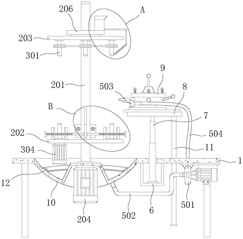
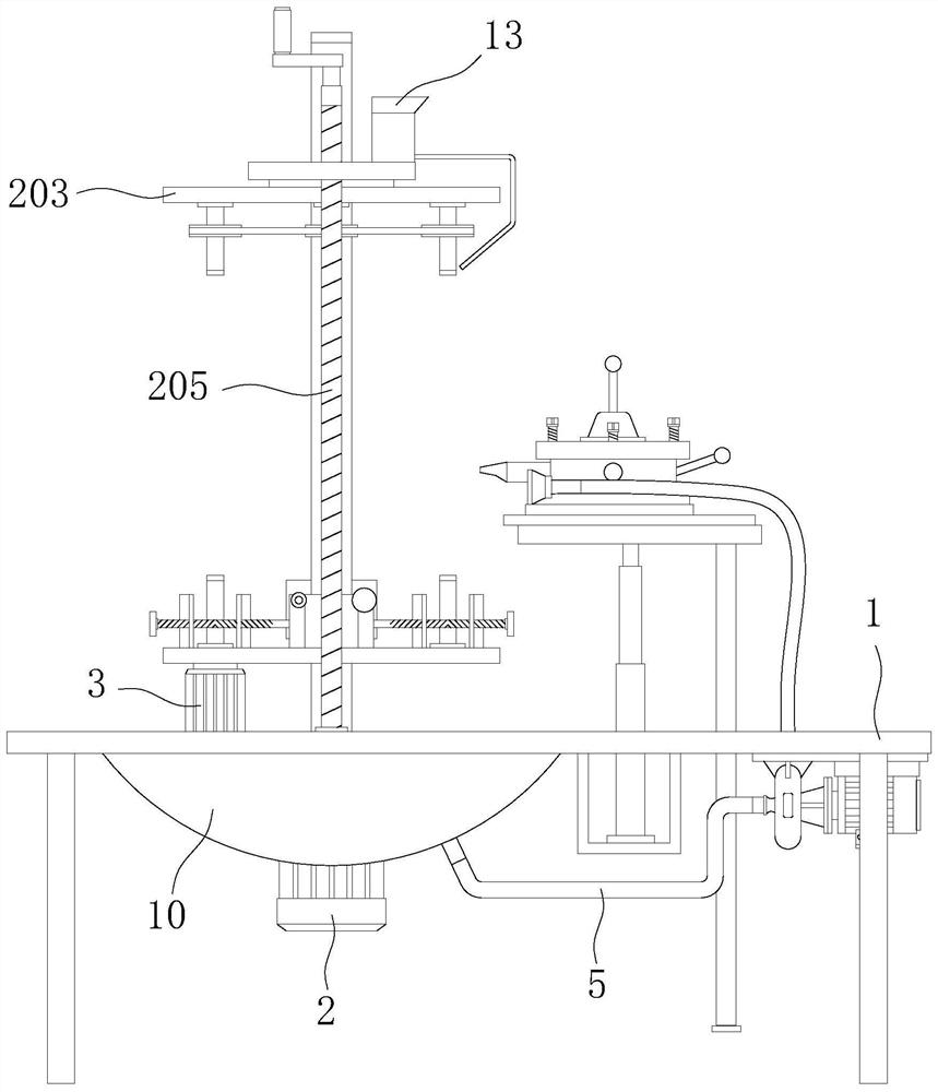
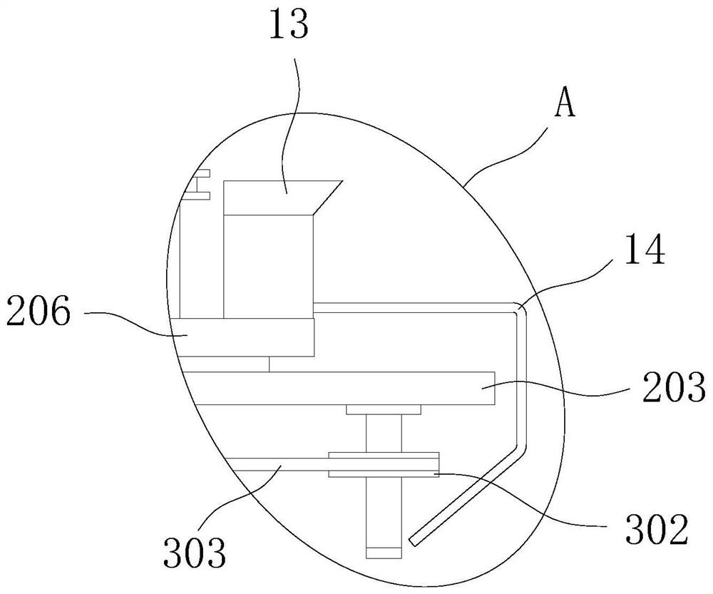
[0024] see Figure 1-5 , the present invention provides a technical solution: a metal parts processing machine tool used in the field of mechanical engineering, comprising a bed 1 on which a rotating clamping mechanism 2, a transmission mechanism 3, an auxiliary clamping mechanism 4 and a circulation flushing mechanism are arranged 5. The outer surface of the bottom of the bed 1 is welded with a mounting frame 6, and the inner bottom of the mounting frame 6 is...


PUM


Abstract

The invention discloses a hardware part machining tool for the field of mechanical engineering, and relates to the technical field of mechanical engineering. The hardware part machining machine tool for the field of mechanical engineering comprises a machine tool body, a rotary clamping mechanism, a transmission mechanism, an auxiliary clamping mechanism and a circulating flushing mechanism are arranged on the machine tool body, a mounting frame is welded to the outer surface of the bottom of the machine tool body, and an electric push rod is welded to the bottom of the inner side of the mounting frame; and a bearing table is welded to the free end of the electric push rod, a guide rail is welded to the outer surface of the top of the bearing table, a sliding base is slidably installed onthe guide rail, and a machining cutter is welded to the outer surface of the top of the sliding base. According to the hardware part machining machine tool for the field of mechanical engineering, repeated workpiece clamping operation is not needed, the labor intensity of operators is relieved, the machining preparation time is shortened, and the production and machining efficiency is improved; and compared with a machining machine tool which does not facilitate continuous operation, the machine tool is higher in practicability and higher in integrality.

Description

technical field [0001] The invention relates to the technical field of mechanical engineering, in particular to a metal parts processing machine tool used in the field of mechanical engineering. Background technique [0002] Machine tool processing refers to the process of relying on the machine tool to ensure the relative motion relationship between the tool and the fixture, and at the same time use the tool to process the workpiece installed on the fixture, but this process is not necessarily cutting or pressure processing, such as rolling on a lathe Flower or Spin. [0003] At present, most of the machine tools used for screw or lead screw processing on the market need to use the top to clamp and fix the two ends of the workpiece before operation. This step requires manual debugging to ensure that the workpiece is clamped smoothly, which wastes a lot of time and is inconvenient. Continuous operation, low processing efficiency, and certain safety hazards, and this type of...

Claims


Application Information

Patent Timeline
IPC IPC(8): B23Q3/06B23Q1/25B23Q7/02B23Q11/00B23Q11/10B08B3/02
CPCB23Q3/062B23Q1/25B23Q7/02B23Q11/0042B23Q11/0064B23Q11/1069B08B3/02
Inventor 郭晓慧
Owner WEIFANG UNIV OF SCI & TECH
Learn More