
Direct-current photocathode ultrafast electron gun with immersed electrostatic lens

An electrostatic lens and electron gun technology, which is applied in the direction of circuits, discharge tubes, electrical components, etc., can solve the problems of reduced spatial resolution of electronic pulses, increased radial radius, and large volume of electron guns, achieving flexible adjustment, reduced device volume, Effects with flexible spatial resolution

Active Publication Date: 2021-03-26
GANNAN NORMAL UNIV
View PDF6 Cites 0 Cited by
  • Summary
  • Abstract
  • Description
  • Claims
  • Application Information

AI Technical Summary

Problems solved by technology

From the perspective of avoiding discharge, the farther the bracket is from the cathode, the better, but this will cause the electron gun to be too bulky
[0004] Due to the existence of electron space repulsion, the electron pulse of the probe will be broadened in the process of drifting to the sample, and the radial radius will increase, resulting in a decrease in the spatial resolution of the electron pulse.
The magnetic lens can focus the electron pulse, but it will cause the electrons in it to rotate perpendicular to the direction of propagation, resulting in a helical path, which is not conducive to the related applications of the "shadow method" and "schlieren method" in ultrafast electron diffraction technology

Method used


Image

  • Direct-current photocathode ultrafast electron gun with immersed electrostatic lens
  • Direct-current photocathode ultrafast electron gun with immersed electrostatic lens
  • Direct-current photocathode ultrafast electron gun with immersed electrostatic lens

Examples


Embodiment Construction

[0021] In order to make the purpose, technical solutions and advantages of the present invention more clear, the present invention will be further described in detail below through specific embodiments in conjunction with the drawings, wherein, in each of the drawings, the same reference numerals represent the same components. It should be understood that the specific embodiments described here are only used to explain the present invention, not to limit the present invention.

[0022] For convenience of description, in figure 1 The coordinate system is drawn in , and the Z axis coincides with the central axis of the electron gun. In this paper, "positive side" means along the figure 1 The shown central axis Z of is facing the face of the incident laser beam 13, while "back side" refers to the face facing away from the incident laser beam 13.

[0023] figure 1 is an external perspective view of the electron gun and surrounding vacuum chamber, figure 2 for along figure 1 T...


PUM

PropertyMeasurementUnit
diameteraaaaaaaaaa
diameteraaaaaaaaaa
diameteraaaaaaaaaa

Abstract

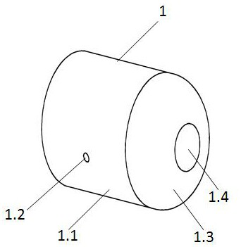
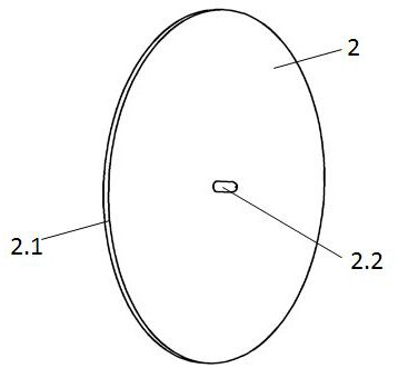
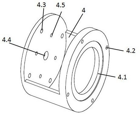
The invention provides a rear-mounted direct-current photocathode ultrafast electronic gun with an immersed electrostatic lens. The rear-mounted direct-current photocathode ultrafast electronic gun comprises a cathode, an anode and an electrostatic lens electrode determined by an electric field and a particle simulation program, and a ceramic disc, a fine ceramic column, an electrostatic lens electrode ceramic support and an electron gun support which are suitable for rear mounting. and the cathode comprises a hollow cylinder, a circular top surface and an arc-shaped connecting surface. The anode comprises two smooth discs and a cylindrical protrusion on the back side, and a through hole is formed in the center of the anode. The electrostatic lens electrode comprises a circular top surface, a cylindrical side surface and an arc-shaped connecting surface, and a through hole is formed in the center. A cylindrical protrusion is arranged in the center of the circular top face, and the topannular face of the protrusion is chamfered. The electronic gun support is of a double-disc connecting structure, a top disc is connected with the fine ceramic column and the ceramic disc, the cathodeis fixed to the ceramic disc, and the anode is placed in a groove in the top disc. The electrostatic lens electrode is fixed on the ceramic support, and the ceramic support is fixed on a disc at thebottom of the support.

Description

technical field [0001] The invention belongs to the field of ultrafast electron diffraction, and in particular relates to a DC photocathode ultrafast electron gun with a submerged electrostatic lens and rear-mounted installation. Background technique [0002] In biology, chemistry, materials, information science, etc., the most critical primary mechanism often occurs at the molecular or sub-molecular structural level, and the time is often in the picosecond to femtosecond range, and the ultrafast detection of the picosecond to femtosecond process usually requires With the help of ultrashort-pulse lasers. Ultrafast electron diffraction (UED) is a technology that uses ultrashort pulse laser to achieve time-resolved pumping and detection. The principle is to use a spectroscopic device to divide the ultrashort pulse laser into two beams, one beam is used to excite the cathode of the electron gun to generate probe electrons, and the other beam induces the reaction area, and the ...

Claims


Application Information

Patent Timeline
Patent Type & Authority Applications(China)
IPC IPC(8): H01J37/06H01J37/065H01J37/12H01J37/295
CPCH01J37/06H01J37/065H01J37/12H01J37/295
Inventor 李梦超刘巧李小菊陈维黄骏王兴权郭勇荣垂才袁寿财卢秀圆
Owner GANNAN NORMAL UNIV
Learn More