Benchmark selection method for minimizing hole site errors of large component group hole machining
A technology for machining hole position and machining datum, which is applied in the field of datum selection with the smallest hole position error in the machining of large parts groups, and can solve the problems affecting the machining accuracy of multi-axis CNC machine tools, the outline of parts is too large, and the processing quality requirements are high.
- Summary
- Abstract
- Description
- Claims
- Application Information
AI Technical Summary
Problems solved by technology
Method used
Image
Examples
Embodiment 1
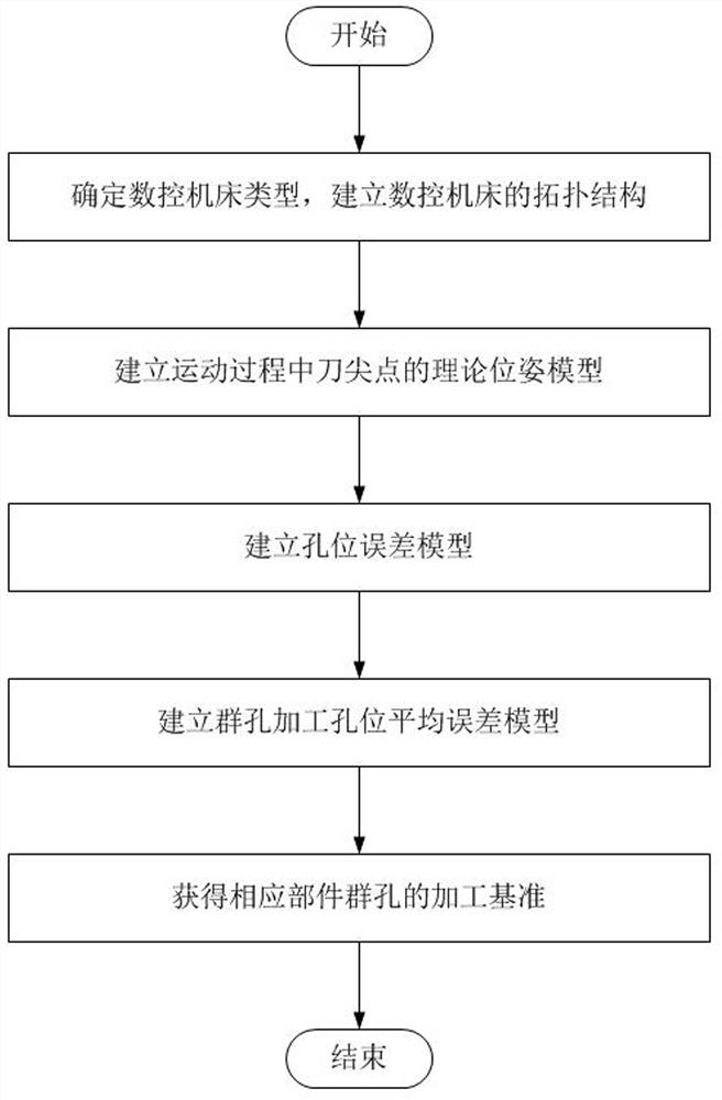
[0074] This embodiment provides a method for selecting the best reference for group hole processing of parts, the specific flow chart is as follows figure 1 As shown, it specifically includes the following steps:
[0075] (1) Determine the type of CNC machine tool, simplify the topology of the machine tool according to the low-order body array method, and perform low-order body numbering on the corresponding motion units.
[0076] (2) Based on the multi-body system theory and the pose error and geometric error of each motion axis, the theoretical pose model of the tool tip point during the motion process is established.
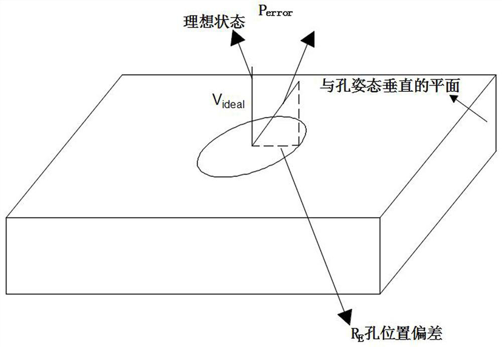
[0077] (3) According to the distance between the actual position of the tool tip point and the theoretical position during the hole making process, and through the projection relationship with the plane perpendicular to the ideal axis, the hole position error model is established.
[0078] (4) There are usually two forms of component group hole processing: ...
Embodiment 2
[0082] In this embodiment, the AC swing-angle five-axis CNC machine tool is taken as an example, and a benchmark is selected for it. The AC swing-angle five-axis CNC machine tool, such as figure 2 As shown, it consists of the following parts: machine bed, X-axis motion unit, Y-axis motion unit, Z-axis motion unit, C-axis motion unit and A-axis motion unit.
[0083] The topology of the five-axis CNC machine tool, such as figure 2 As shown, specifically: machine bed 0→X-axis motion unit 1→Y-axis motion unit 2→Z-axis motion unit 3→C-axis motion unit 4→A-axis motion unit 5, wherein the C-axis motion unit 4 pivotally Connected to the Z-axis motion unit 3, the A-axis motion unit 5 is pivotally connected to the C-axis motion unit 4, the processing spindle is fixedly connected to the A-axis 5, and the tool is placed and clamped on the processing spindle. For the convenience of error modeling, each feed axis is fixedly connected to the motion coordinate system, and the fixedly conne...
PUM
 Abstract
Description
Claims
Application Information
 - R&D
- Intellectual Property
- Life Sciences
- Materials
- Tech Scout
- Unparalleled Data Quality
- Higher Quality Content
- 60% Fewer Hallucinations
Browse by: Latest US Patents, China's latest patents, Technical Efficacy Thesaurus, Application Domain, Technology Topic, Popular Technical Reports.
© 2025 PatSnap. All rights reserved.Legal|Privacy policy|Modern Slavery Act Transparency Statement|Sitemap|About US| Contact US: help@patsnap.com


