
Thermal shrinkage detection device for thermal shrinkage film manufacturing

A technology of heat shrinkable film and detection device, applied in sampling device, material thermal expansion coefficient and other directions, can solve the problems of low detection efficiency, inability to realize automation, easy loss of temperature of detection box, etc., to increase accuracy, improve detection efficiency, reduce heat loss effect

Inactive Publication Date: 2021-03-26
吴日香
View PDF0 Cites 0 Cited by
  • Summary
  • Abstract
  • Description
  • Claims
  • Application Information

AI Technical Summary

Problems solved by technology

[0003] However, directly using the detection box for detection requires manual placement of the test sample in the detection box to fix, the detection efficiency is relatively low, and the automation of detection cannot be realized, and it cannot meet the needs of automatic detection of the processing table on the heat shrinkable film production line. Cutting and sampling are carried out on the platform. For the safety of personnel and equipment, the production line needs to be shut down, so that sampling inspection and heat shrinkable film manufacturing cannot be carried out at the same time, and the heat shrinkable film is directly placed in the inspection box for heating inspection. When the box is effectively sealed, the temperature in the test box is easy to lose, and the temperature in the test box cannot be guaranteed to be stable, which will affect the detection effect of the heat shrinkable film

Method used


Image

  • Thermal shrinkage detection device for thermal shrinkage film manufacturing
  • Thermal shrinkage detection device for thermal shrinkage film manufacturing
  • Thermal shrinkage detection device for thermal shrinkage film manufacturing

Examples


Embodiment Construction

[0026] In order to make the technical means, creative features, goals and effects achieved by the present invention easy to understand, the present invention will be further described below in conjunction with specific embodiments.

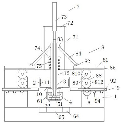
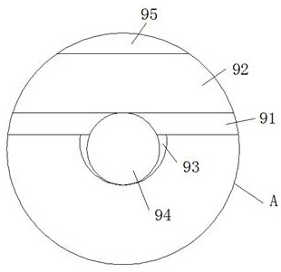
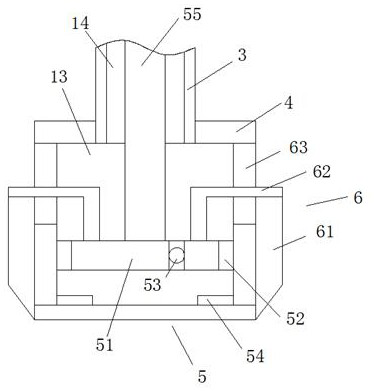
[0027] Such as Figure 1-Figure 7 As shown, a thermal shrinkage detection device for heat shrinkable film manufacturing according to the present invention includes a fixed bracket 1, a detection box 2, a telescopic column 3, a sampling head 4, an adsorption mechanism 5, a cutting mechanism 6, and a telescopic mechanism 7 , a linkage mechanism 8, a sealing mechanism 9 and a heating plate 11, the fixed bracket 1 is fixedly connected to the upper end of the processing table, the middle position of the lower end of the fixed bracket 1 is fixedly connected with a detection box 2, and the middle position of the upper end of the fixed bracket 1 is set There is a through hole 12, a telescopic column 3 is slidably connected in the through hole 12, a telesc...


PUM


Abstract

The invention relates to the field of shrink film manufacturing and detection, in particular to a thermal shrinkage detection device for thermal shrinkage film manufacturing, which comprises a fixingsupport, a detection box, a telescopic column, a sampling head, an adsorption mechanism, a cutting mechanism, a telescopic mechanism, a linkage mechanism, a sealing mechanism and a heating plate, andis characterized in that the fixing support is fixedly connected to the upper end of a processing table; a detection box is fixedly connected to the middle of the lower end of the fixing support, a through hole is formed in the middle of the upper end of the fixing support, the telescopic column is slidably connected into the through hole, and a telescopic groove is formed in the telescopic column. A telescopic rod of the adsorption mechanism is pushed to slide through the output end of a hydraulic cylinder of the telescopic mechanism, so that the sampling head can be pushed to slide downwards, the shrinkage film is adsorbed, and finally the shrinkage film is driven to enter the detection box for shrinkage detection, the detection automation is realized, and the troublesome operation of manually sampling and then placing the shrinkage film into the detection box is avoided; therefore, the detection efficiency of the thermal shrinkage film is improved.

Description

technical field [0001] The invention relates to the field of detection of shrink film manufacture, in particular to a heat shrinkage detection device for heat shrink film manufacture. Background technique [0002] Heat shrinkable film is a kind of packaging film processed and formed by polyester compound. It is used on the outer packaging of daily commodities, because it can protect the packaged items from impact, and has the functions of preventing rain, moisture and rust. It can also make the product with beautifully printed outer packaging, and at the same time it can well show the good image of the manufacturer. During the production process, when testing the heat shrinkable film, it is usually used to place the heat shrinkable film in the inspection box Inside, and the shrink film is deformed by heating, and the shrinkage of the heat shrinkable film is judged by the deformation of the heat shrinkable plate. [0003] However, directly using the detection box for detecti...

Claims


Application Information

Patent Timeline
IPC IPC(8): G01N25/16G01N1/04
CPCG01N1/04G01N25/16
Inventor 吴日香
Owner 吴日香
Learn More