Building decoration material lifting device convenient to assemble
A construction and support board technology, applied in the processing of construction materials, construction, hoisting devices, etc., can solve the problems of low efficiency, falling off, etc., and achieve the effects of ensuring safety, easy disassembly and assembly, and saving labor intensity
- Summary
- Abstract
- Description
- Claims
- Application Information
AI Technical Summary
Problems solved by technology
Method used
Image
Examples
Embodiment 1
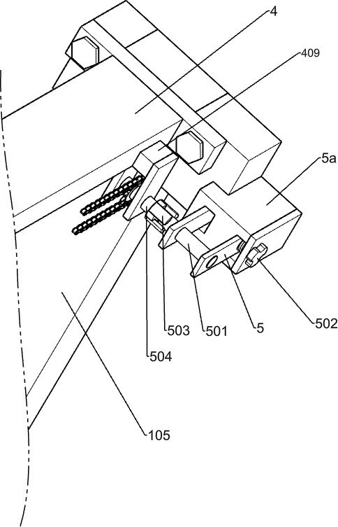
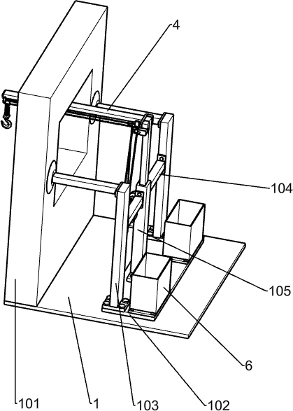
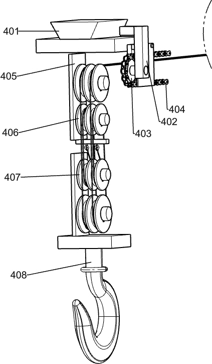
[0029] An easy-to-assemble material lifting device for building decoration, such as Figure 1-7 As shown, it includes a base plate 1, a support wall 101, a first support plate 102, a support frame 103, a first support rod 104, a second support rod 105 and a bearing box 6, and the support wall 101 is fixedly installed on the left side of the base plate 1. The first support plate 102 is fixedly installed on the upper right side of the base plate 1, and the two support frames 103 are fixedly installed on the front and rear sides of the upper part of the first support plate 102, and the first support rod 104 is fixedly installed on the side between the two support frames 103. In the middle position, the second support bar 105 is fixedly installed in the middle position of the first support plate 102, the second support bar 105 is fixedly connected with the middle position of the first support bar 104, and the two bearing boxes 6 are fixedly installed in the first support plate 102 ...
Embodiment 2
[0032] On the basis of Example 1, such as Figure 2-3 As shown, the control mechanism includes a second support plate 2, a motor 201, a speed change mechanism, a first pulley 202, a first belt 203, a third support plate 204, a drum 208 and a wire rope 209, and the second support plate 2 is fixedly installed In the middle of the left part of the second support bar 105, the motor 201 is fixedly installed on the second support plate 2, and the third support plate 204 is fixedly installed on the left side of the second support bar 105 close to the second support plate 2. On the lower side, the speed change mechanism is fixedly mounted on the third support plate 204, the first pulley 202 on the left side is fixedly mounted on the output shaft of the motor 201, and the first pulley 202 on the right side is fixedly mounted on the speed change mechanism. The belt 203 is wound on the two first pulleys 202 , the two drums 208 are fixedly installed in the middle of the third support plat...
Embodiment 3
[0035] On the basis of Example 2, such as image 3 As shown, the transmission mechanism includes a first shaft 205, a first spur gear 206, a second spur gear 207, a second shaft 210, a third spur gear 211 and a fourth spur gear 212, and the first shaft 205 is rotatably mounted. On the left rear side of the third support plate 204, the first spur gear 206 is fixedly mounted on the rear side of the first shaft 205, the second spur gear 207 is fixedly mounted on the front side of the first shaft 205, and the second shaft 210 is rotatably installed on the left rear side of the third support plate 204, the second shaft 210 is located above the first shaft 205, the third spur gear 211 is fixedly installed on the rear side of the second shaft 210, the third spur gear 211 meshes with the first spur gear 206, the fourth spur gear 212 is fixedly mounted on the front side of the second shaft 210, the fourth spur gear 212 meshes with the second spur gear 207, and the two rotating drums 20...
PUM
 Abstract
Description
Claims
Application Information
 - R&D Engineer
- R&D Manager
- IP Professional
- Industry Leading Data Capabilities
- Powerful AI technology
- Patent DNA Extraction
Browse by: Latest US Patents, China's latest patents, Technical Efficacy Thesaurus, Application Domain, Technology Topic, Popular Technical Reports.
© 2024 PatSnap. All rights reserved.Legal|Privacy policy|Modern Slavery Act Transparency Statement|Sitemap|About US| Contact US: help@patsnap.com


