Permanent magnet speed regulator based on mobile magnetic steel

A technology of permanent magnet governor and magnetic steel, which is applied in permanent magnet clutches/brakes, electric brakes/clutches, asynchronous induction clutches/brakes, etc. It can solve the problems of easy failure of permanent magnets, large moment of inertia, and large vibration of equipment and other issues, to achieve the effect of stable and more reliable product equipment, simple adjustment structure, and improved safety

Pending Publication Date: 2021-03-23
陈莉芳
View PDF0 Cites 0 Cited by
  • Summary
  • Abstract
  • Description
  • Claims
  • Application Information

AI Technical Summary

Problems solved by technology

[0003] The existing permanent magnet governor mainly includes cylindrical permanent magnet governor and disc permanent magnet governor. To change the effective part of the coupling between the permanent magnet rotor and the conductor rotor, and then adjust the torque, this requires a large axial space to facilitate the relative axial movement between the permanent magnet rotor and the conductor rotor; and the disc permanent magnet The speed governor adjusts the torque by adjusting the air gap between the disc-shaped permanent magnet rotor and the conductor rotor, and then realizes the speed regulation of the load. It also requires a large axial space to adjust the air gap. The product shaft The size of the axis is large, which brings great inconvenience to the site transformation; in addition, when the speed is adjusted, the permanent magnet rotor needs to be moved, the equipment cantilever is long, the vibration is large, the bearing is easy to be damaged, and the reliability of the equipment is not good; when adjusting, due to the quality of the permanent magnet rotor , large moment of inertia, easy to impact; the load of the adjustment device and the adjustment bearing are easily damaged due to excessive force; the equipment has large vibration, high heat generation, and the permanent magnet is easy to fail; at the same time, it is necessary to overcome the effect of large permanent magnetic attraction when adjusting the air gap
This makes it difficult to apply in some places with limited space

Method used


Image

  • Permanent magnet speed regulator based on mobile magnetic steel
  • Permanent magnet speed regulator based on mobile magnetic steel
  • Permanent magnet speed regulator based on mobile magnetic steel

Examples


Embodiment

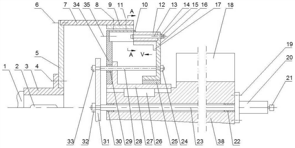
[0047] The moving magnet permanent magnet speed governor of this embodiment includes a cylindrical conductor rotor, a permanent magnet rotor fixing part arranged on the inner circumference of the cylindrical conductor rotor, and a shaft that drives the permanent magnet rotor moving part to move relative to the permanent magnet rotor fixing part. to the mobile agency.

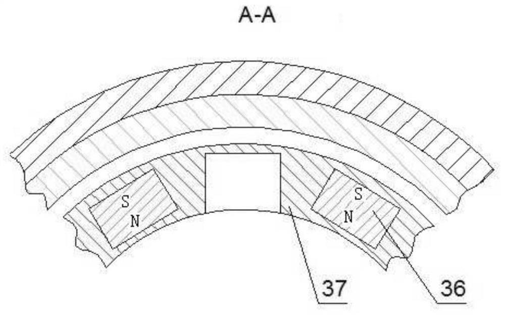
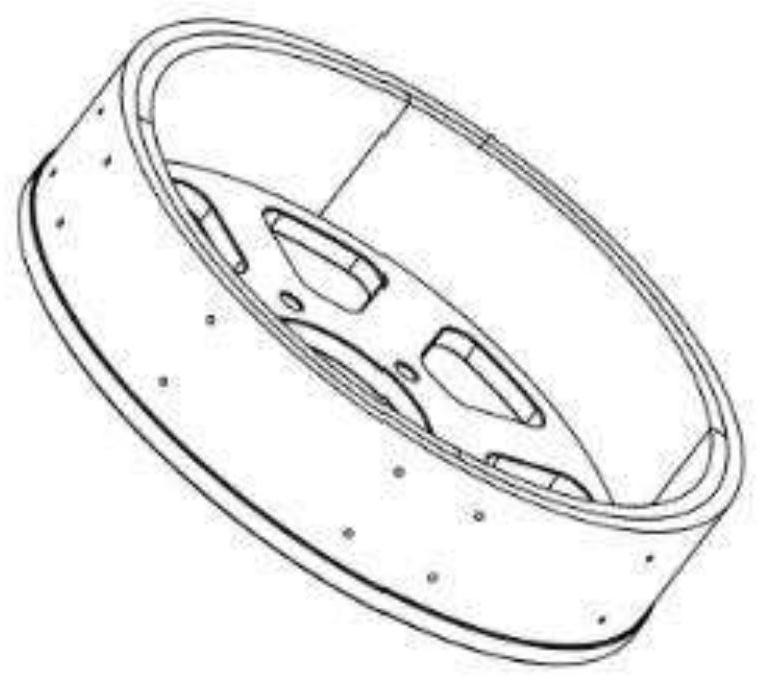
[0048] The cylindrical conductor rotor is mounted on the load shaft through a load coupling, and a copper conductor ring is installed on the outer circumference of the cylindrical conductor rotor. Wherein, the permanent magnet rotor is installed on the motor drive shaft through the motor coupling, and permanent magnets uniformly distributed along the circumference are arranged inside the permanent magnet rotor. There is an air gap between the conductor rotor and the permanent magnet rotor without contact, and the axial movement mechanism is coaxially arranged with the permanent magnet rotor; the axial movement m...


PUM


Abstract

A permanent magnet speed regulator based on movable magnetic steel comprises a conductor rotor, a permanent magnet rotor and an axial movement magnetic flux adjusting mechanism; a radial gap exists between the conductor rotor and the permanent magnet rotor; the conductor rotor synchronously rotates along with a first transmission shaft; the permanent magnet rotor synchronously rotates along with asecond transmission shaft; the permanent magnet rotor comprises a permanent magnet rotor fixed part and a permanent magnet rotor moving part; a fixed magnetic group is arranged on the permanent magnet rotor fixed part; and a moving magnetic group is arranged on the permanent magnet rotor moving part; the axial moving magnetic flux adjusting mechanism comprises a moving mechanism; the permanent magnet rotor moving part is connected with the moving mechanism; the moving mechanism drives the permanent magnet rotor moving part to axially move, and the moving magnetic group is axially inserted into or moved out of the fixed magnetic group. The whole adjusting structure is simpler and smaller in size; and the axial moving mechanism is simple in composition; and maintenance is convenient in actual application.

Description

technical field [0001] The invention belongs to the technical field of permanent magnet speed regulation, in particular to a permanent magnet speed regulator for moving magnet steel. Background technique [0002] In large-scale mining, petrochemical, electric power and metallurgy industries, due to the need for energy saving and environmental protection, permanent magnet speed control devices are more and more widely used. The permanent magnet speed control device can adapt to various harsh environments, including places with large grid voltage fluctuations, serious harmonics, flammable, explosive, humid, dusty, etc., and can adjust the speed of the load online to meet the actual operation needs of the system and realize speed regulation Energy saving, speed regulation range 0-98%, energy saving rate 10%-65%. When working, the motor drives the conductor rotor of the permanent magnet governor to rotate, and the copper conductor on the conductor rotor cuts the magnetic induct...

Claims


Application Information

Patent Timeline
IPC IPC(8): H02K49/04H02K49/10
CPCH02K49/043H02K49/106
Inventor 陈莉芳
Owner 陈莉芳
Why Eureka
Try Eureka