
Square three-frequency antenna device and communication equipment

An antenna device, a square technology, is applied to the antenna grounding device, the device that enables the antenna to work in different bands at the same time, the antenna and other directions, which can solve the problems of easy damage, the bandwidth of the multi-frequency antenna cannot meet the requirements, and the external antenna is bulky.

Active Publication Date: 2021-03-19
GREE ELECTRIC APPLIANCES INC
View PDF14 Cites 2 Cited by
  • Summary
  • Abstract
  • Description
  • Claims
  • Application Information

AI Technical Summary

Problems solved by technology

Electromagnetic signals are sent and received through the antenna. Due to the disadvantages of large size and easy damage of the external antenna, more and more electronic devices use built-in antennas.
With the development of wireless communication devices, traditional built-in single-frequency antenna devices can no longer meet people's needs for wireless communication. In order to meet the multi-band communication capabilities, it is usually hoped that the system will integrate multiple antennas or use a single broadband antenna to cover More communication frequency bands, reducing the occupied space, so as to achieve the purpose of reducing costs, and at the same time require the antenna to have high gain and high bandwidth performance
[0003] However, the bandwidth of multi-frequency antennas in the prior art often does not meet the requirements, and the size is too large, most of which are three-dimensional structures, and the use environment has certain limitations

Method used


Image

  • Square three-frequency antenna device and communication equipment
  • Square three-frequency antenna device and communication equipment
  • Square three-frequency antenna device and communication equipment

Examples


Embodiment Construction

[0034] In order to make the purpose, technical solution and advantages of the present invention clearer, the technical solution of the present invention will be described in detail below. Apparently, the described embodiments are only some of the embodiments of the present invention, but not all of them. Based on the embodiments of the present invention, all other implementations obtained by persons of ordinary skill in the art without making creative efforts fall within the protection scope of the present invention.

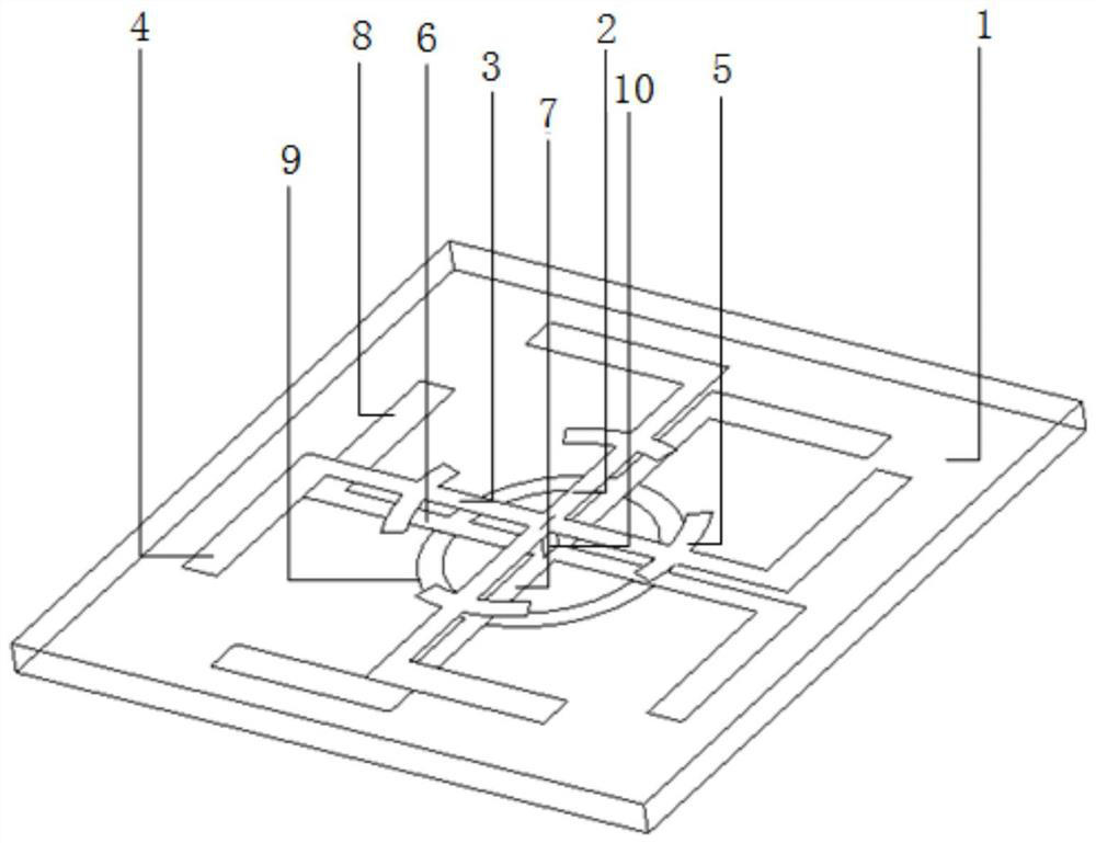
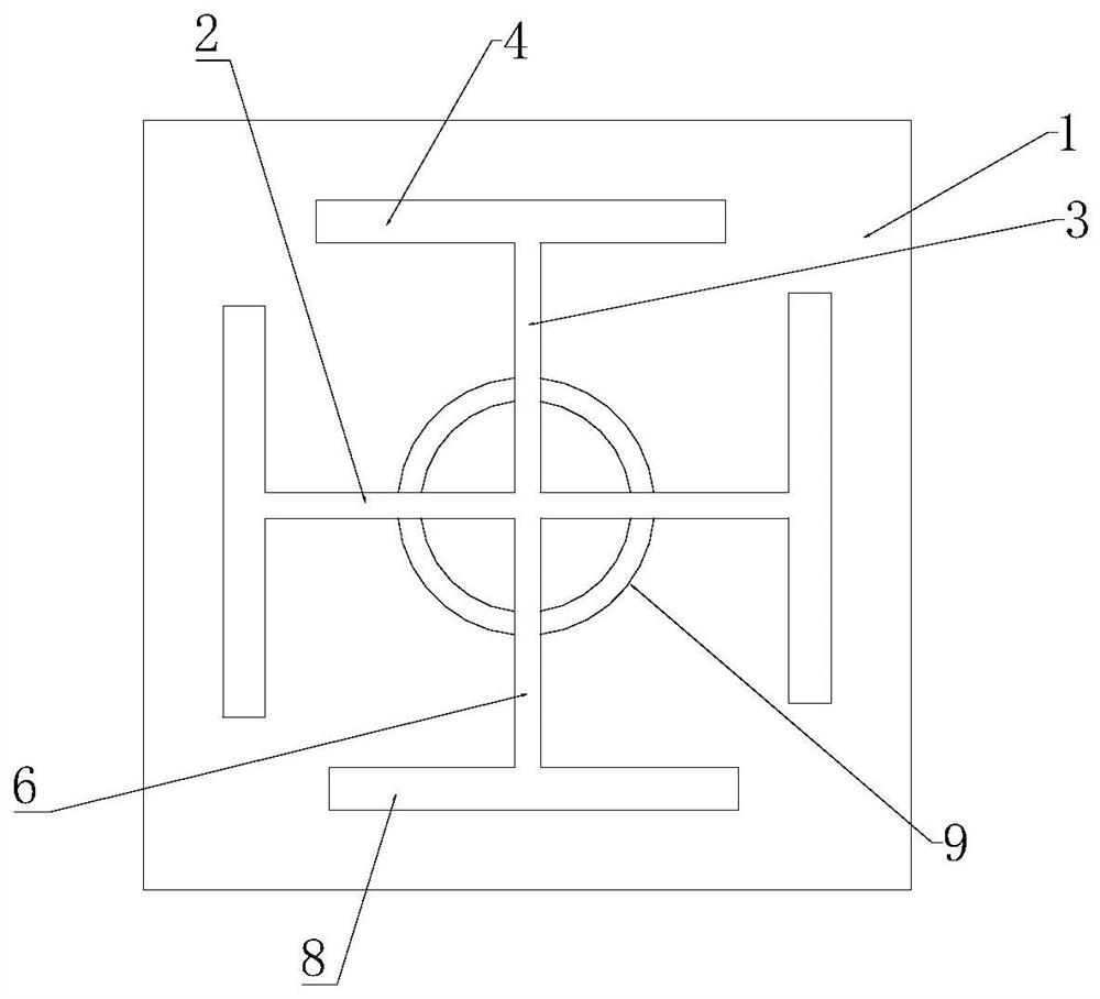
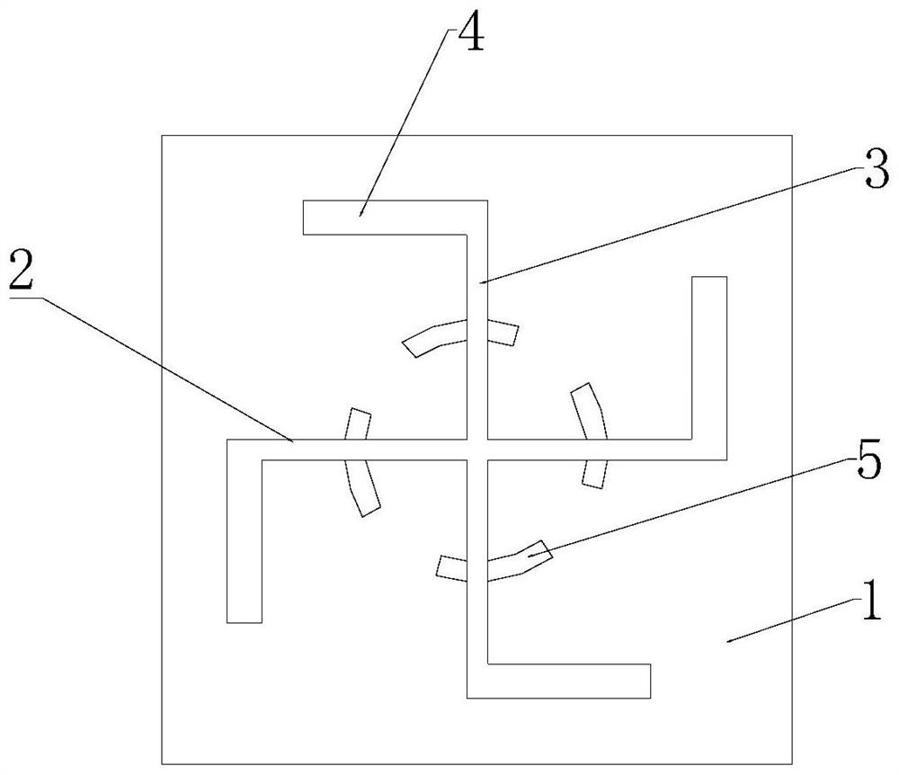
[0035] Such as Figure 1 to Figure 4 As shown, a square tri-band antenna device described in this embodiment includes:

[0036] Dielectric layer 1, radiation part, ground part and excitation part;

[0037] The radiating part is arranged on the upper surface of the dielectric layer 1, and the grounding part is arranged on the lower surface of the dielectric layer 1; the excitation part is used to connect the radiating part and the grounding part to form curren...


PUM

PropertyMeasurementUnit
Lengthaaaaaaaaaa
Widthaaaaaaaaaa
Lengthaaaaaaaaaa

Abstract

The invention relates to a square three-frequency antenna device and communication equipment. The device comprises a dielectric layer, a radiation part, a grounding part, and an excitation part, wherein the radiation part is arranged on the upper surface of the dielectric layer, and the grounding part is arranged on the lower surface of the dielectric layer; the excitation part is used for connecting the radiation part with the grounding part to form a current loop; the radiation part comprises a first rectangular resonance body and a second rectangular resonance body which are perpendicular to each other; and the grounding part comprises a first rectangular metal patch and a second rectangular metal patch which are perpendicular to each other. The square three-frequency antenna device isa built-in onboard antenna with three frequency bands, the antenna device utilizes the square and annular structures and the vertical rectangular resonators to realize coverage of multiple frequency bands, and the antenna device is high in gain, small in occupied size, relatively high in bandwidth, easy to manufacture and capable of radiating backwards, so energy efficiency of the antenna device is improved on the whole.

Description

technical field [0001] The invention relates to the technical field of communication components, in particular to a square tri-frequency antenna device and communication equipment. Background technique [0002] With the rapid development of wireless communication technology and the increasingly widespread application of radio equipment, antennas, as equipment for receiving and transmitting radio waves, are a key component in wireless communication systems. Electromagnetic signals are sent and received through antennas. Due to the disadvantages of large size and easy damage of external antennas, more and more electronic devices use built-in antennas. With the development of wireless communication devices, traditional built-in single-frequency antenna devices can no longer meet people's needs for wireless communication. In order to meet the multi-band communication capabilities, it is usually hoped that the system will integrate multiple antennas or use a single broadband ante...

Claims


Application Information

Patent Timeline
IPC IPC(8): H01Q1/38H01Q1/48H01Q5/28H01Q21/06
CPCH01Q1/38H01Q1/48H01Q21/061H01Q5/28
Inventor 杨宏红符超姜义重陶运黄树文
Owner GREE ELECTRIC APPLIANCES INC
Learn More