Semi-closed capacitor overheating prevention device with dust removal function

A semi-closed, capacitor technology, applied in the field of capacitors, can solve problems such as affecting the heat dissipation of capacitors, reducing air-cooling heat dissipation, safety hazards, etc., to improve the heat dissipation effect, avoid accidents, and prevent deformation.

Active Publication Date: 2021-03-19
巨华(广东)电气有限公司
View PDF3 Cites 0 Cited by
  • Summary
  • Abstract
  • Description
  • Claims
  • Application Information

AI Technical Summary

Problems solved by technology

[0002] The power of current large-capacity capacitors is usually high, and it is easy to deform due to high temperature during long-term work, which has certain safety hazards. At the same time, the surface of the capacitor is very easy to attract a large amount of dust due to static electricity, which seriously affects For the heat dissipation of the capacitor, if a dust cover is added to the capacitor, the effect of air cooling and heat dissipation will be reduced. On the other hand, the self-healing capacitor can prevent the work of all capacitors from stopping due to overheating, but the capacity of the self-healing capacitor will decrease. Decrease with use, affecting the working performance of the corresponding device

Method used


Image

  • Semi-closed capacitor overheating prevention device with dust removal function
  • Semi-closed capacitor overheating prevention device with dust removal function
  • Semi-closed capacitor overheating prevention device with dust removal function

Examples


Embodiment Construction

[0017] Bonded below Figure 1-5 The present invention will be described in detail, in which it is convenient for the description, the orientation of the following statement is as follows: The above-mentioned left and right directions figure 1 The projection relationship of the projection is consistent with the front and back and so on.

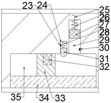
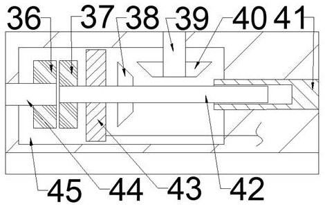
[0018] A semi-closed capacitor with dust removal function, including a dust tank 10, including a dust tank 10, and a dust tank inner cavity in which an opening is provided to the left. 11. The lower side of the dust box inner cavity 11 is connected to a support plate chamber 17, and the lower side of the dust box inner cavity 11 is connected to a ring gear seat annular cavity 48 located on the left side of the support sheet chamber. The laminar chamber 48 sidewall is slidably coupled to the end surface ring gear seat 47, and the end surface of the end surface is fixedly connected to the end surface ring gear 46, and the end surface of the end surf...


PUM


Abstract

The invention relates to the related field of capacitors, and discloses a semi-closed capacitor overheating prevention device with a dust removal function. The device comprises a dustproof box body, adustproof box inner cavity with a leftward opening is arranged in the dustproof box body, and a support plate cavity is communicated with the lower side of the dustproof box inner cavity. The lower side of an inner cavity of the dustproof box communicates with a gear ring seat annular cavity located on the left side of the supporting plate cavity, the side wall of the gear ring seat annular cavity is in sliding fit connection with an end face gear ring seat, and the upper end face of the end face gear ring seat is fixedly connected with an end face gear ring. A plurality of annular cavity springs are fixedly connected between the lower end face of the end face gear ring base and the lower end wall of the gear ring base annular cavity. When the temperature of the inner cavity of the dustproof box exceeds a certain value, the large turntable drives the two working capacitors to rotate for half a circle to realize the exchange of the working capacitors, so that the deformation of the original working capacitors due to overheating is prevented, and the cleaning sliding plate is exchanged to drive the cleaning brush to move downwards or upwards while the capacitors are exchanged; therefore, the surface of the working capacitor is cleaned.

Description

Technical field [0001] The present invention relates to the field of capacitors, in particular a semi-closed capacitor with dust removal function. Background technique [0002] The current powerful capacitors are generally higher. It is easy to deform due to high temperature during long hours, and there is a certain safety hazard. At the same time, the surface of the capacitor is very easy to attract a large amount of dust due to static electricity, which seriously affects The heat dissipation of the capacitor, if the dust cover is added to the capacitor, it reduces the effect of air-cooled heat dissipation. On the other hand, the self-healing capacitor can prevent all capacitors from stopping due to overheating, but the capacity of the self-healing capacitor will increase As used, it is reduced, affecting the working performance of the corresponding device. Inventive content [0003] It is an object of the present invention to provide a semi-closed capacitor anti-prevention dev...

Claims


Application Information

Patent Timeline
IPC IPC(8): H01G2/14H01G2/18H01G2/08B08B1/00
CPCH01G2/14H01G2/18H01G2/08B08B1/30B08B1/12
Inventor 杜家主
Owner 巨华(广东)电气有限公司
Why Eureka
Try Eureka