Device, system and method for soil form test under seepage action
The technology of a test device and a test system is applied in the field of soil form test devices under the action of seepage.
- Summary
- Abstract
- Description
- Claims
- Application Information
AI Technical Summary
Problems solved by technology
Method used
Image
Examples
Embodiment 1
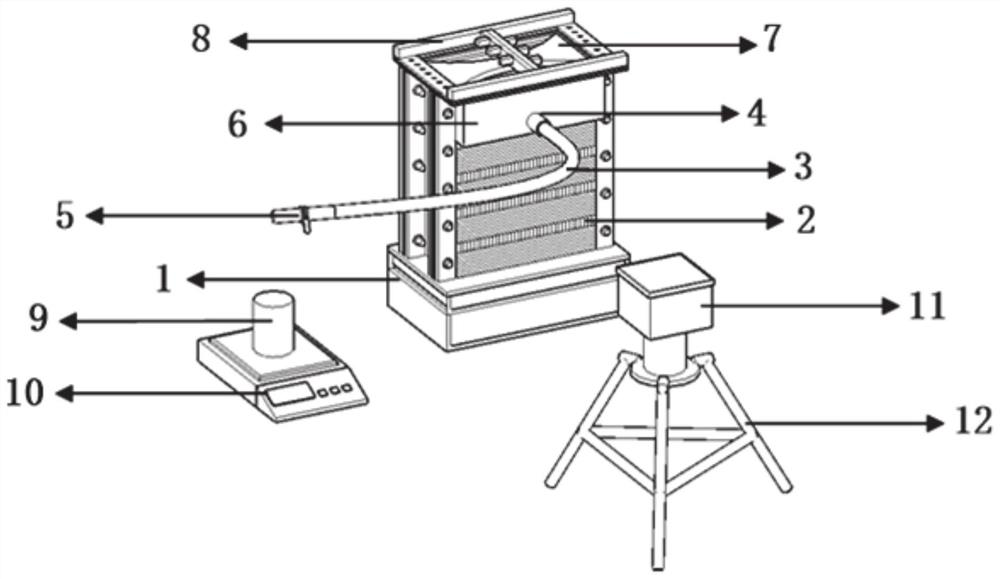
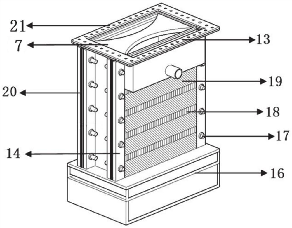
[0045] This embodiment provides a soil form test device under seepage action, such as figure 1 and figure 2 As shown, it includes a steady flow chamber 1, a seepage destruction chamber 2, a mobile pressurization module 14, and a water tank 6. The seepage destruction chamber 2 is fixed above the steady flow chamber 1, and the water tank 6 is installed on the side of the seepage destruction chamber 2; the seepage destruction chamber 2 A plurality of mobile pressurization modules 14 are installed on the side.
[0046] The steady flow chamber 1 is a cuboid structure, and the inside is a cavity. A partition plate 16 is installed inside the steady flow chamber 1, and the partition plate 16 is provided with a number of through holes; the steady flow chamber 1 is divided into upper and lower layers by the partition plate 16, The lower layer is used to fill water, and the upper layer is used to fill coarse sand to prevent direct erosion of the soil by water flow.
[0047] In this em...
Embodiment 2
[0056] This embodiment provides a soil form test system under seepage action, such as figure 1 Shown, comprise the test device described in embodiment one, also comprise measuring cylinder 9, balance 10, digital camera 11, grating sensor 25, laser displacement sensor 8, measuring cylinder 9, balance 10 form weighing module; Laser displacement sensor 8, grating The sensor 25 and the digital camera 10 constitute a detection module.
[0057] When in use, the measuring cylinder 9 is placed above the balance 10, and the measuring cylinder 9 corresponds to the water outlet below the water outlet pipe 3 for measuring the flow rate. The laser displacement sensor is used to monitor the deformation of the soil surface during the test and is installed above the cover plate 21 . The grating sensor 25 is used to measure the internal deformation of the soil; in this embodiment, the model of the laser displacement sensor 8 is LT-9501H, and the model of the grating sensor 25 is NZS-DTS.
[...
Embodiment 3
[0062] This embodiment provides a test method for seepage failure of tunnel excavation face, using the test system described in Embodiment 2, such as Figure 6 shown, including the following steps:
[0063] (1) The soil samples are naturally air-dried, crushed, crushed, and screened.
[0064] (2) Weigh the dyeing agent and water according to the ratio of 100:1 and the optimum water content, mix the soil sample, water and dyeing agent evenly, and put them into a plastic cylinder to moisten for 24 hours.
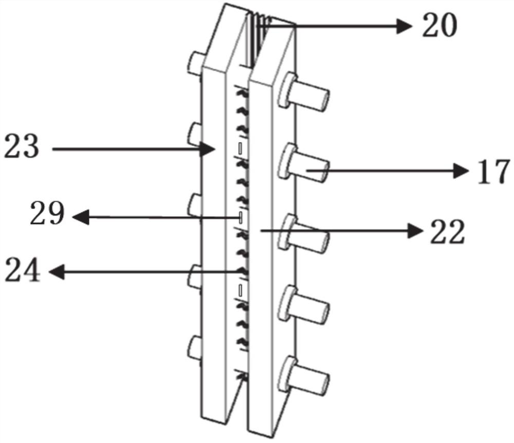
[0065] (3) Connect the first pressurizing plate 22 and the second pressurizing plate 23 in the mobile pressurizing module 14 with the extension plate of the seepage destruction chamber 2 through bolts 17, and install the telescopic member 20, the spring 24, and the rubber gasket 26 ; The rubber gasket is set between the first pressure plate 22 and the steady flow chamber 1 .
[0066] (4) Install the partition plate 16 in the steady flow chamber 1, and put coarse sand into th...
PUM
 Abstract
Description
Claims
Application Information
 - R&D
- Intellectual Property
- Life Sciences
- Materials
- Tech Scout
- Unparalleled Data Quality
- Higher Quality Content
- 60% Fewer Hallucinations
Browse by: Latest US Patents, China's latest patents, Technical Efficacy Thesaurus, Application Domain, Technology Topic, Popular Technical Reports.
© 2025 PatSnap. All rights reserved.Legal|Privacy policy|Modern Slavery Act Transparency Statement|Sitemap|About US| Contact US: help@patsnap.com


