
Wire harness SR structure suitable for narrow space and high in assembly precision and processing technology

A narrow space, processing technology, applied to the parts of the connecting device, coupling device, electrical components, etc., can solve problems such as poor contact, SR cracking, camera water ingress, etc., to increase stability and increase plug-in pull-out force , Effective use of space

Inactive Publication Date: 2021-03-12
珠海琴创电子科技有限公司
View PDF0 Cites 0 Cited by
  • Summary
  • Abstract
  • Description
  • Claims
  • Application Information

AI Technical Summary

Problems solved by technology

[0002] SR is often used on the wire harness. The camera wire harness SR and PCB are connected by connectors. There are high requirements for the strength, weather resistance, waterproof performance, and dimensional accuracy of the connectors. Otherwise, poor contact and SR cracks often occur. Many problems such as water entering the camera
[0003] Due to the limited space, some SRs with special shapes and small volumes are required, such as the narrow space of the left and right rearview mirrors. SRs of this shape are required to effectively avoid the body structure parts behind the camera, and also meet the waterproof requirements. The outer mold of special-shaped SRs During the injection molding process, due to the small structure, the injection pressure will break the inner core wire, and the core wire will be rushed to the edge of the SR by the injection pressure at the place where the glue is thin, so that the core wire cannot be covered, and the core wire will be leaked and the plastic will be punched. The phenomenon of poor contact in the terminal of the plastic shell

Method used


Image

  • Wire harness SR structure suitable for narrow space and high in assembly precision and processing technology
  • Wire harness SR structure suitable for narrow space and high in assembly precision and processing technology
  • Wire harness SR structure suitable for narrow space and high in assembly precision and processing technology

Examples


Embodiment Construction

[0039] The following will clearly and completely describe the technical solutions in the embodiments of the present invention with reference to the accompanying drawings in the embodiments of the present invention. Obviously, the described embodiments are only some, not all, embodiments of the present invention. Based on the embodiments of the present invention, all other embodiments obtained by persons of ordinary skill in the art without making creative efforts belong to the protection scope of the present invention.

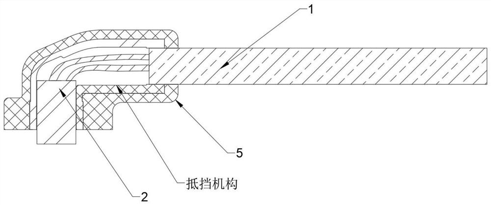
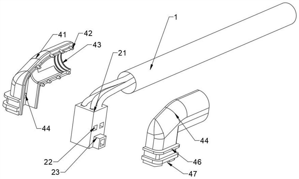
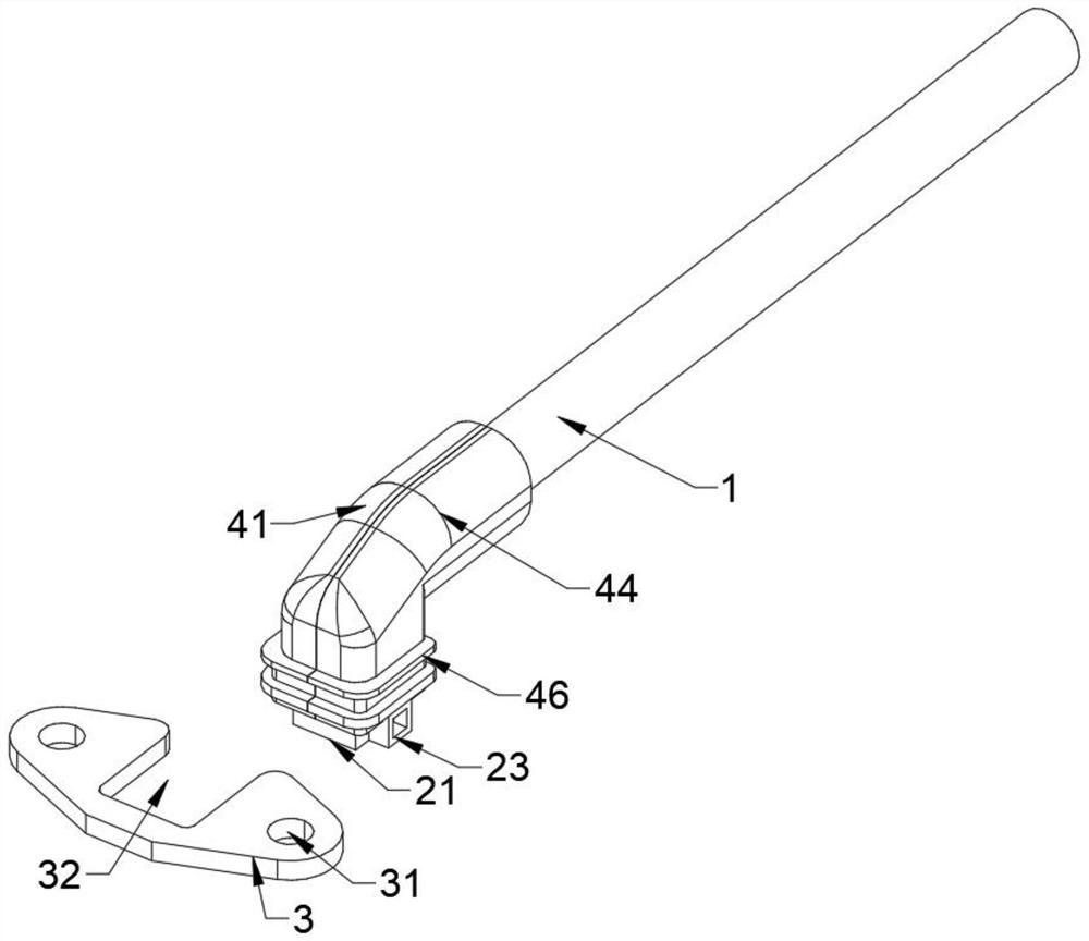
[0040] see Figure 1-10 , the present invention provides a technical solution: a wire harness SR structure suitable for narrow space assembly with high precision, including a wire harness 1 and a plug-in 2, characterized in that: one end of the wire harness 1 is provided with a plug-in 2, and both sides of the plug-in 2 are provided with resisting mechanisms, The outer side of the resisting mechanism is clamped with a metal plate 3, and the outer side of the r...


PUM


Abstract

The invention discloses a wire harness SR structure suitable for narrow space and high in assembly precision and a processing technology, the wire harness SR structure comprises a wire harness and a plug-in and is characterized in that one end of the wire harness is provided with the plug-in, the two sides of the plug-in are provided with blocking mechanisms, the outer sides of the blocking mechanisms are clamped with hardware plates, and the outer sides of the blocking mechanisms and the hardware plates are provided with SR outer molds. One end of the wire harness is fixedly installed with the plug-in, the side surface of the plug-in is clamped with the blocking mechanisms, the side surface of the wire harness is in clearance fit with the blocking mechanism,s the side surfaces of the blocking mechanisms are clamped with the hardware plates, the inner walls of the SR outer molds are bonded with the hardware plates, the blocking mechanisms and the wire harness, the plug-in comprises a rubber shell, and grooves are formed in two sides of the rubber shell. And each blocking mechanism comprises a right inner mold, clamping keys are evenly welded to the plane of the right inner mold, and a left inner mold is clamped to the outer walls of the clamping keys. According to the invention, the wire harness SR structure has the characteristics of good injection molding effect and good sealing effect.

Description

technical field [0001] The invention relates to the technical field of vehicle equipment, in particular to a wire harness SR structure and processing technology suitable for narrow spaces with high assembly accuracy. Background technique [0002] SR is often used on the wire harness. The camera wire harness SR and PCB are connected by connectors. There are high requirements for the strength, weather resistance, waterproof performance, and dimensional accuracy of the connectors. Otherwise, poor contact and SR cracks often occur. There are many problems such as water entering the camera. [0003] Due to the limited space, some SRs with special shapes and small volumes are required, such as the narrow space of the left and right rearview mirrors. SRs of this shape are required to effectively avoid the body structure parts behind the camera, and also meet the waterproof requirements. The outer mold of special-shaped SRs During the injection molding process, due to the small str...

Claims


Application Information

Patent Timeline
Patent Type & Authority Applications(China)
IPC IPC(8): H01R13/405H01R13/502H01R13/52B29C45/14B29C45/26
CPCB29C45/14065B29C45/26H01R13/405H01R13/502H01R13/5221
Inventor 王冬梅
Owner 珠海琴创电子科技有限公司
Learn More