
Filter cloth production cutting equipment

An equipment and filter cloth technology, applied in the field of filter cloth production and cutting equipment, can solve the problems of single filter cloth molding style, cutting stuck, damaged, etc., and achieve the effect of expanding the scope of processing objects, improving the stability and the degree of use.

Active Publication Date: 2021-03-12
阜阳全科智能技术设计有限公司
View PDF6 Cites 1 Cited by
  • Summary
  • Abstract
  • Description
  • Claims
  • Application Information

AI Technical Summary

Problems solved by technology

[0003] 1. The overall function of the cutting structure used is relatively simple, the filter cloth is formed in a single style, and the device as a whole is underutilized. At the same time, the filter cloth is in a relatively loose state when it is cut, and it is prone to cutting jams and other phenomena, so the overall cutting quality is low. At the same time, it is less necessary to perform corresponding tightening treatment on filter cloths with different degrees of elasticity;
[0004] 2. The filter cloth is deflected during the laying process and the filter cloth slides during the cutting process, so that the cutting quality of the filter cloth is reduced. When the filter cloth is pressed and limited, it is easy to cause the filter cloth to be over-pressed. The cloth is overstretched or damaged

Method used


Image

  • Filter cloth production cutting equipment
  • Filter cloth production cutting equipment
  • Filter cloth production cutting equipment

Examples


Embodiment Construction

[0035] The embodiments of the present invention will be described in detail below with reference to the accompanying drawings, but the present invention can be implemented in many different ways as defined and covered by the claims.

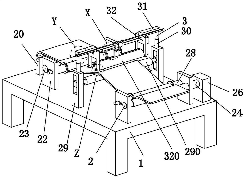
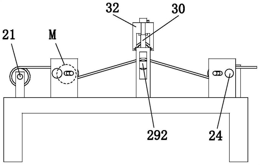
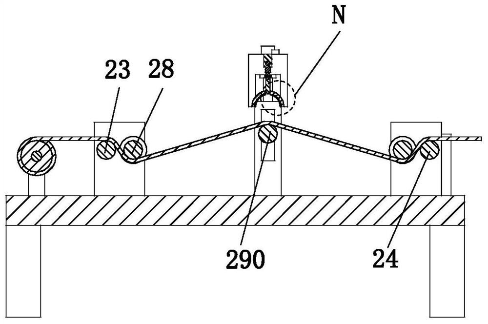
[0036] Such as Figure 1 to Figure 12 As shown, a filter cloth production and cutting equipment includes a working table 1, a retractable mechanism 2 and a cutting mechanism 3. The lower end of the described working table 1 is installed on the existing working ground, and the upper end of the working table 1 is provided with a retractable Mechanism 2, the middle part of retractable mechanism 2 is provided with cutting mechanism 3.

[0037] The retractable mechanism 2 includes a No. 1 vertical plate 20, a telescopic inner shaft 21, a No. 2 vertical plate 22, a rotating shaft 23, a fixed shaft 24, a clamping column 25, a No. 1 motor 26, a connecting rod 27, a final shaft 28, and a No. 3 Riser 29 and roller 290, No. 1 vertical plate 20 is symmetric...


PUM


Abstract

The invention relates to filter cloth production cutting equipment. The filter cloth production cutting equipment comprises a worktable, a retracting and releasing mechanism and a cutting mechanism, the lower end of the worktable is installed on existing working ground, the retracting and releasing mechanism is arranged at the upper end of the worktable, and the cutting mechanism is arranged in the middle of the retracting and releasing mechanism. The filter cloth is produced and cut by adopting the design concept of a multi-mode production structure, the whole equipment can cut the filter cloth into sections for forming and can also cut the filter cloth into strips for forming, so that the equipment has the advantage that one machine has multiple functions, the whole processing object range of the equipment is expanded, the use degree is improved, the position of a cutter can be adaptively and accurately regulated and controlled according to the forming requirement in the cutting andstrip forming process, the arranged retracting and releasing mechanism can clamp and fix the filter cloth to prevent the filter cloth from sliding in the cutting process, thus the relative standing degree of the filter cloth is improved, and the cutting and forming quality is improved to some extent.

Description

technical field [0001] The invention relates to the technical field of filter cloth production, in particular to a filter cloth production and cutting equipment. Background technique [0002] Filter cloth refers to the filter medium made of natural fibers or synthetic fibers. Commonly used materials include cotton, hemp, wool, cocoon silk, asbestos fibers, glass fibers and some synthetic fibers, such as cotton canvas, twill and wool. Woven woolen cloth, etc., in a broad sense, filter cloth also includes metal mesh or filter mesh, mainly used in air filtration and dust removal, dust collection, air purification, environmental protection, in smelters, chemical plants, sugar , dyes, medicine, food and other industries are widely used. The main production process of filter cloth includes basic processes such as twisting - warping - hedging - weaving - cloth repairing - shaping (calendering) - cutting and making, but in the production of filter cloth The following problems occur...

Claims


Application Information

Patent Timeline
Patent Type & Authority Applications(China)
IPC IPC(8): D06H7/00
CPCD06H7/00
Inventor 刘小英
Owner 阜阳全科智能技术设计有限公司
Learn More