Self-centering device for pressing cylinder sleeve into wheel

A self-centering, wheel technology, applied in the direction of metal processing, metal processing equipment, manufacturing tools, etc., can solve the problems of error, positioning fixture error, large interference, etc., to reduce waste, improve press-fitting yield, improve center to neutral effect

Pending Publication Date: 2021-03-12
CITIC DICASTAL
View PDF0 Cites 0 Cited by
  • Summary
  • Abstract
  • Description
  • Claims
  • Application Information

AI Technical Summary

Problems solved by technology

[0002] After the machining of some wheel products, the cylinder liner needs to be press-fitted at the position of the bolt hole, and the cylinder liner is firmly assembled in the bolt hole by means of interference fit. Due to the existence of machining errors, it is impossible for several bolt holes on the wheel to be accurate. In the theoretically correct position, there will always be a small amount of error within the allowable deviation range of the drawing. In addition, there is also a certain error in the positioning fixture on the press for assembling the cylinder liner. The entire assembly process system including the wheel is due to the comprehensive effect of various errors. , resulting in the cylinder liner of some cylinder liner products being pressed into the wheel, there is a certain offset between the axis of the cylinder liner and the axis of the bolt hole of the wheel, which makes the interference between the cylinder liner and the bolt hole uneven, and some The position interference is slightly large, and some positions are small. The position with large interference usually presses the material on the inner wall of the bolt hole out of the bolt hole, so that there are some small protrusions on the flange surface of the wheel, which does not meet the requirements of the wheel. The flatness of the flange surface and the requirement of concave, which in turn affect the assembly effect of the vehicle installation

Method used


Image

  • Self-centering device for pressing cylinder sleeve into wheel
  • Self-centering device for pressing cylinder sleeve into wheel
  • Self-centering device for pressing cylinder sleeve into wheel

Examples


Embodiment Construction

[0023] It should be noted that, in the case of no conflict, the embodiments of the present invention and the features in the embodiments can be combined with each other.

[0024] The technical solutions of the present invention will be clearly and completely described below with reference to the accompanying drawings and in conjunction with the embodiments. Apparently, the described embodiments are only some, not all, embodiments of the present invention. Based on the embodiments of the present invention, all other embodiments obtained by persons of ordinary skill in the art without making creative efforts belong to the protection scope of the present invention.

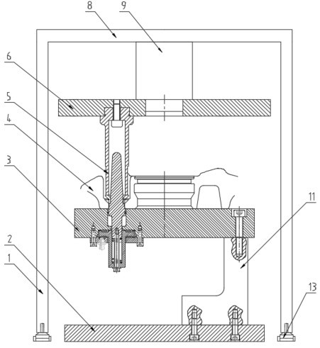
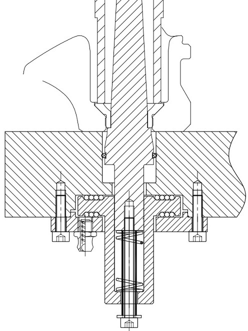
[0025] Refer below Figure 1 to Figure 4 The self-centering device for the cylinder liner wheel of the embodiment of the present invention is described in combination with the embodiments.

[0026] A self-centering device for pressing cylinder liner wheels, including a frame, a bottom plate 2 is arranged on the bott...


PUM


Abstract

The invention discloses a self-centering device for for pressing a cylinder sleeve into a wheel. The self-centering device for pressing the cylinder sleeve into the wheel comprises a rack; a bottom plate is arranged at the bottom of the rack; a top plate is arranged at the top of the rack; a flat plate is arranged on the bottom plate; a self-centering system is arranged on the flat plate; the self-centering system comprises a positioning column elastically connected to the flat plate; a hydraulic cylinder is arranged on the top plate; and a down-pressing hollow column is connected to a position, downward corresponding to a positioning column, at the output end of the hydraulic cylinder. According to the self-centering device for pressing the cylinder sleeve into the wheel in the scheme provided by the invention, the center centering performance when the cylinder sleeve is pressed into a wheel bolt hole can be improved, waste products generated by bolt hole material extrusion due to misalignment are reduced, and the press-fitting yield is increased.

Description

technical field [0001] The invention relates to the technical field of wheel assembly, in particular to a self-centering device for cylinder liner wheels. Background technique [0002] After the machining of some wheel products, the cylinder liner needs to be press-fitted at the position of the bolt hole, and the cylinder liner is firmly assembled in the bolt hole by means of interference fit. Due to the existence of machining errors, it is impossible for several bolt holes on the wheel to be accurate. In the theoretically correct position, there will always be a small amount of error within the allowable deviation range of the drawing. In addition, there is also a certain error in the positioning fixture on the press for assembling the cylinder liner. The entire assembly process system including the wheel is due to the comprehensive effect of various errors. , resulting in the cylinder liner of some cylinder liner products being pressed into the wheel, there is a certain of...

Claims


Application Information

Patent Timeline
IPC IPC(8): B23P19/027
CPCB23P19/027
Inventor 王军刘啸郭建东蔡卫民杜海东刘鸣华郑尧徐佐武汉琦张艳新
Owner CITIC DICASTAL
Why Eureka
Try Eureka