
A continuous molding device for filter center pipe

A molding device and center tube technology, applied in the field of air filters, can solve the problems of low production efficiency of intermittent processing, difficulty in meeting modern processing, waste of manpower and material resources, etc., to improve processing quality, compact structure, and prevent surface localization deformation effect

Active Publication Date: 2021-07-20
佛山市豹王滤芯制造有限公司
View PDF14 Cites 0 Cited by
  • Summary
  • Abstract
  • Description
  • Claims
  • Application Information

AI Technical Summary

Problems solved by technology

The production efficiency of intermittent processing is low, and it is easy to cause adverse effects on the product during the transfer and handling process, and it wastes manpower and material resources. It has become increasingly difficult to meet the requirements of modern processing.

Method used


Image

  • A continuous molding device for filter center pipe
  • A continuous molding device for filter center pipe
  • A continuous molding device for filter center pipe

Examples


Embodiment

[0035] Embodiment: A continuous molding device for a central pipe of a filter.

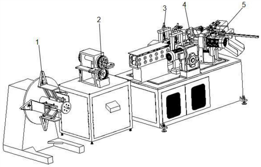
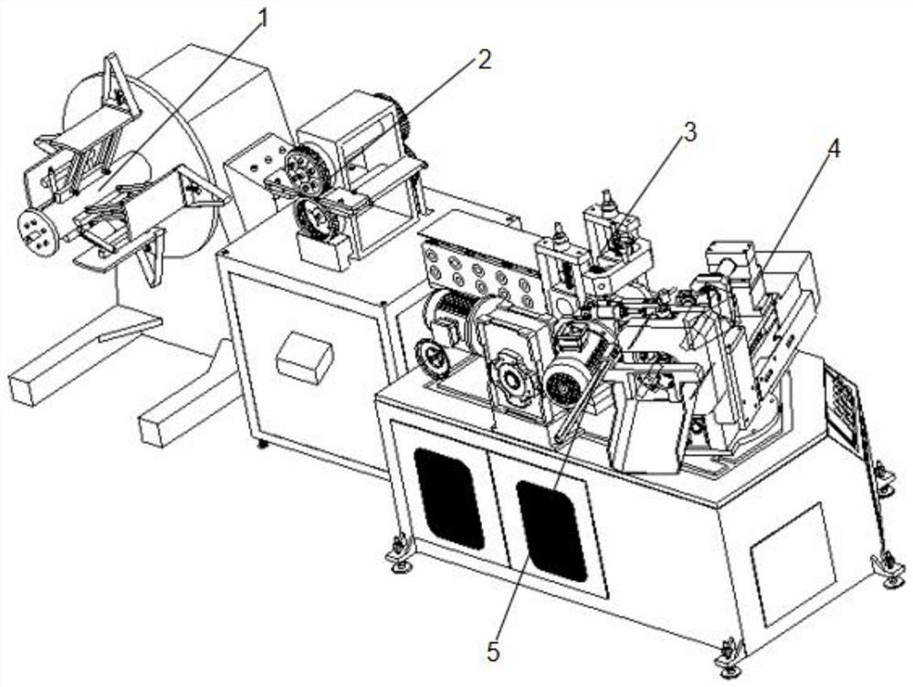
[0036] refer to Figure 1 to Figure 14 As shown, a continuous molding device for filter center pipe, including:

[0037] Unwinding device 1, described unwinding device 1 comprises unwinding frame 11, and unwinding shaft 13 is installed on the described unwinding frame 11, and rotating disk 12 is fixed on the afterbody of unwinding shaft 13, and is installed on described unwinding shaft 13 There are four fixed installation blocks 14 that are distributed in a circular array around the center of the unwinding shaft 13, each fixed installation block 14 is correspondingly equipped with a support 15, the top of the support 15 is equipped with a support plate 16, and the tail of the support plate 16 is equipped with End block 17, the front end of unwinding shaft 13 is equipped with a front sealing plate 18; in the actual work process, the metal strip roll is placed on the support plate 16 and positioned...


PUM


Abstract

The invention provides a continuous forming device for a central tube of a filter, comprising an unwinding device; a punching device installed on the right side of the unwinding device; a pushing device installed on the right side of the punching device; and a pushing device installed on the right side of the pushing device The coiling device; the cutting device installed at the front end of the coiling device, the cutting device includes a rotating shell, the center of the rotating shell is provided with a center hole matching the coiling shaft, and the cutting wheel is fixed on the On the installation shaft, one end of the installation shaft is fixed on the rotating shell, the positioning guide wheel is installed on one side of the center hole of the rotating shell, and the pneumatic pull rod is installed on one side of the rotating shell, the pneumatic pull rod and the rotating shell They are fixedly connected by a tie rod shaft. The continuous forming device of the central tube of the filter can realize automatic unwinding, punching, stable feeding, automatic coiling and cutting of the coiled plate, realize continuous processing and forming of the central tube, and greatly improve the processing efficiency and quality of the central tube.

Description

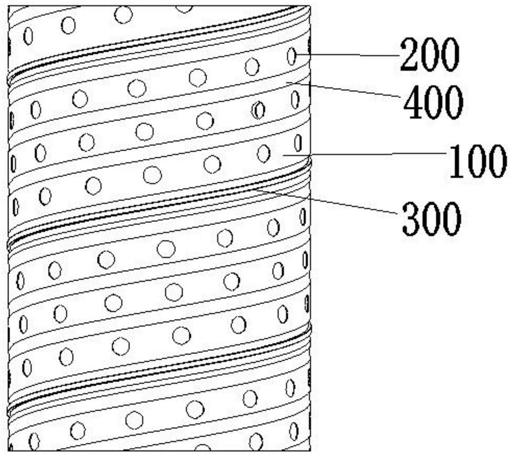
technical field [0001] The invention relates to the technical field of air filters, in particular to a continuous forming device for a center pipe of a filter. Background technique [0002] The central tube is one of the parts of the filter, which plays a role in supporting the filter element and making it difficult to deform. The central tube is full of small holes, so that the liquid or gas waiting to be filtered can pass through smoothly, so the rigidity of the central tube and the passage of the circulating medium are particularly important. [0003] The structure of the central tube of the spiral filter commonly used in the market is as follows: figure 1 As shown, it mainly includes a central tube body 100 formed by a spiral coiled tube. The surface of the central tube body 100 is uniformly provided with through holes 200. The central tube body 100 is formed by a spiral coiled tube. The sides 300 are butted, and the center pipe body 100 also needs to be rolled with ou...

Claims


Application Information

Patent Timeline
Patent Type & Authority Patents(China)
IPC IPC(8): B21D35/00B21D28/26B21D17/04B21D11/06B21C47/18B21C47/28
CPCB21C47/18B21C47/28B21D11/06B21D17/04B21D28/26B21D35/001B21D35/002
Inventor 黄兆强程志深唐进杰李世和罗雄章陈启标
Owner 佛山市豹王滤芯制造有限公司
Learn More