
A mold for cable manufacturing and molding

A cable manufacturing and mold technology, which is applied in the field of cable manufacturing and molding molds, can solve the problems of not involving the cable cooling function, wasting working time, and reducing work efficiency, so as to improve the quality of injection molding, increase production efficiency, and improve work efficiency. Effect

Active Publication Date: 2022-02-11
天津市飞亚凤达线缆科技有限公司
View PDF5 Cites 0 Cited by
  • Summary
  • Abstract
  • Description
  • Claims
  • Application Information

AI Technical Summary

Problems solved by technology

[0003] However, there are deficiencies in the above-mentioned technology. In the above-mentioned structure, the cooling function of the cable is not involved during the production of the cable. The speed of natural cooling and solidification is relatively slow, which wastes working time and reduces work efficiency.

Method used


Image

  • A mold for cable manufacturing and molding
  • A mold for cable manufacturing and molding
  • A mold for cable manufacturing and molding

Examples


no. 1 example

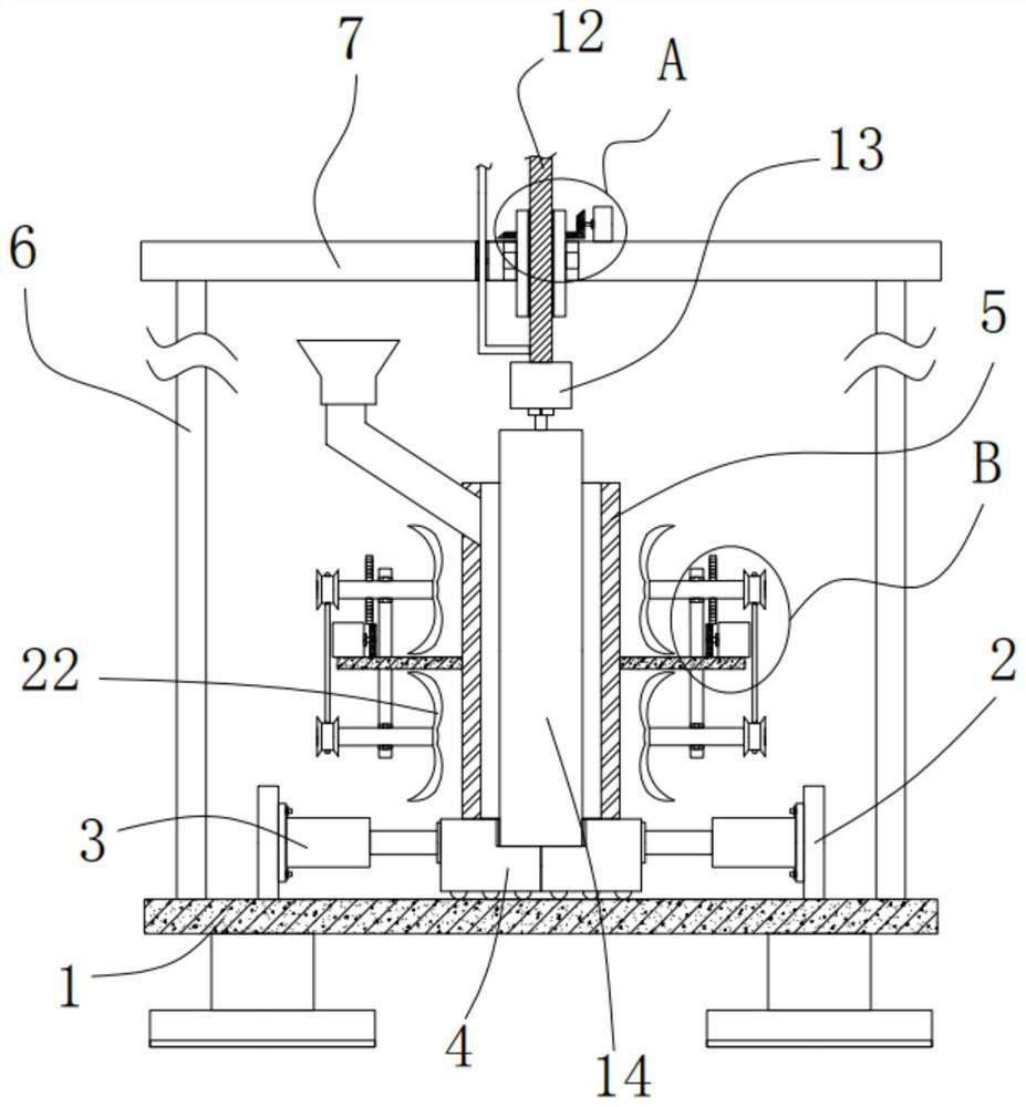
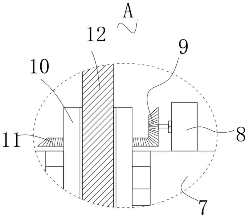
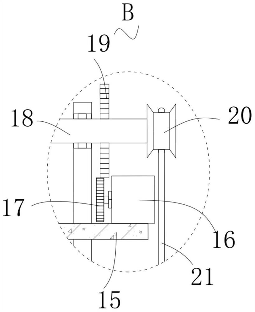
[0046] Please refer to Figure 1 to Figure 4 , in the first embodiment of the present invention, the mold used for cable manufacturing and molding includes: a base plate 1; The top of the top; two hydraulic cylinders 3, two hydraulic cylinders 3 are respectively fixedly installed on the side of two bar-shaped fixed blocks-2 close to each other; two semicircular support blocks 4, two semicircular support blocks 4 respectively Fixedly installed on the output shafts of two hydraulic cylinders 3; two semi-arc movable molds 5, two semi-arc movable molds 5 are respectively fixedly installed on the tops of two semicircular support blocks 4; Put plate 6, two vertical type put plate 6 all be fixedly installed on the top of base plate 1; Square top plate 7, square top plate 7 are fixedly installed on the top of two vertical type put plate 6; The motor one 8 is fixedly installed on the top of the square top plate 7; the first bevel gear 9, the first bevel gear 9 is fixedly installed on ...

no. 2 example

[0058] Based on the mold for cable manufacturing and molding provided in the first embodiment of the present application, the second embodiment of the application proposes another mold for cable manufacturing and molding, and the second embodiment is only an example of the first embodiment. In a further solution of the invention, the implementation of the second embodiment will not affect the independent implementation of the first embodiment. The second embodiment of the present invention will be further described below in conjunction with the drawings and implementation methods.

[0059] Please refer to Figure 5-Figure 6 , in the second embodiment of the present invention, the mold used for cable manufacturing and molding also includes: two first placement plates 23, and the two first placement plates 23 are respectively fixedly installed on the two vertical placement plates 6 On the side close to each other, the top of the first placement plate 23 is placed with a cooling ...


PUM


Abstract

The invention provides a mold for manufacturing and molding cables. The mold used for cable manufacturing and molding includes: a base plate; two strip-shaped fixed blocks one, and the two strip-shaped fixed blocks one are fixedly installed on the top of the base plate; two hydraulic cylinders, the two hydraulic cylinders respectively Fixedly installed on one side of two strip-shaped fixed blocks close to each other; two semicircular support blocks, the two semicircular support blocks are respectively fixedly installed on the output shafts of the two hydraulic cylinders; two semi-arc moving The mould, the two semi-arc movable molds are respectively fixedly installed on the top of the two semicircular support blocks; the two vertical placement plates are fixedly installed on the top of the base plate. The mold for cable manufacturing and molding provided by the invention can improve the uniformity of cable thickness and ensure product quality; it can effectively cool the cable after it is made and shaped, improve work efficiency, and is simple and convenient to operate.

Description

technical field [0001] The invention relates to the technical field of moulds, in particular to a mold used for manufacturing and forming cables. Background technique [0002] Cable is a general term for optical cables, cables and other items. There are many uses of cables, mainly used for multiple functions such as control installation, connection equipment, and power transmission. It is a common and indispensable thing in daily life. Because cables are charged, Therefore, the installation needs to be particularly careful. In the related art, a mold forming device for cable manufacturing and molding is disclosed, which includes a mold base, a cable inner cladding forming cavity and a cable outer cladding forming cavity, which are sequentially arranged on the mold base along the cable conveying direction. Above, the end of the cable inner cladding molding cavity communicates with the head end of the cable outer cladding molding cavity through a middle channel; the first heat...

Claims


Application Information

Patent Timeline
Patent Type & Authority Patents(China)
IPC IPC(8): H01B13/00
CPCH01B13/0036
Inventor 陈云
Owner 天津市飞亚凤达线缆科技有限公司
Learn More