
Generator charging circuit, battery isolator, charger, inverter and carrier

A charging circuit and generator technology, which is applied in the electronic field, can solve problems such as bad charging of secondary batteries, different voltages of secondary batteries, and large power consumption.

Pending Publication Date: 2021-03-05
天津九九电子有限公司
View PDF0 Cites 0 Cited by
  • Summary
  • Abstract
  • Description
  • Claims
  • Application Information

AI Technical Summary

Problems solved by technology

[0018] 2. Charging the auxiliary battery: the charging current of the general battery is less than 0.1C, that is, 10% of the capacity
Obviously, traditional isolators can't do it, because there is no limitless flow function at all;
[0019] 3. The auxiliary battery is not fully charged: because the three-stage or five-stage charging of the auxiliary battery cannot be realized
Obviously, traditional isolators cannot do it;
[0020] 4. The auxiliary battery has no temperature compensation and temperature protection: the battery manufacturer requires temperature compensation, which has a specific temperature coefficient
Obviously, traditional isolators cannot do it;
[0021] 5. Different types of secondary batteries cannot be charged: for example, the main battery is lead-acid, and the secondary battery is lithium battery;
[0022] 6. The voltage of the auxiliary battery is different and cannot be charged: for example, the main battery is 24V, and the auxiliary battery is 12V;
[0023] 7. High power consumption: Traditional isolators rely on relays to work, and the work of relays requires a large current, often greater than 30~50mA
The forward conduction of the diode also consumes a lot of power: for example, 50A charging, the diode voltage drop is 0.5V, and the power consumption is 50*0.5=25W;
[0024] 8. Short service life: because the relay has contacts;
[0025] 9. Large size and high cost: Power diodes and relays are large and expensive

Method used


Image

  • Generator charging circuit, battery isolator, charger, inverter and carrier
  • Generator charging circuit, battery isolator, charger, inverter and carrier
  • Generator charging circuit, battery isolator, charger, inverter and carrier

Examples


Embodiment Construction

[0096] A generator charging circuit:

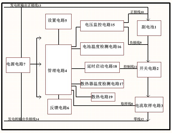
[0097] figure 1 It is a structural diagram of the generator charging circuit of the present invention.

[0098] The charging main circuit according to the current direction: generator output positive pole line 13-secondary battery 1-switching circuit 2-current sampling circuit 3-generator output negative pole line 14.

[0099] According to the different positions of the auxiliary battery 1, the switch circuit 2, and the current sampling circuit 3, there are 5 other layout modes for the charging main circuit. Figure 7 It is another three structural diagrams of the charging main circuit of the present invention. These layouts can realize the PWM mode charging current limit of the sub-battery 1, but the corresponding circuit can be slightly adjusted. figure 1 The layout is just one of them.

[0100] The switch circuit 2 includes a switch tube and a drive circuit. The most commonly used switching tube is the mos field effect tube, which...


PUM


Abstract

The invention discloses a generator charging circuit, a battery isolator, a charger, an inverter and a carrier. The charging circuit comprises a management circuit, a switch circuit, a time delay circuit, a voltage monitoring circuit and a power supply circuit. The management circuit determines the delayed charging time and the charging current according to the detected output voltage value of a generator, ensures that the voltage of the main battery is not undervoltage and the output of the generator is not overloaded, and charges the auxiliary battery according to the power as high as possible. By means of PWM mode control, the auxiliary battery is a charging system completely independent of the main battery, and can be charged completely according to the charging curve technical requirements of battery manufacturers.

Description

technical field [0001] It belongs to the field of electronic technology, and specifically relates to electric parts of automobiles and ships. Background technique [0002] For ease of description, the present invention defines the following terms: [0003] "Switch tube" refers to an electronic component in the present invention, which is a general term for triode, Darlington tube, and field effect tube; [0004] "Voice chip" is the general term for the following three types of chips: dedicated voice chip, memory with voice data, or MCU with voice function. Some voice chips use "binding" (COB), such as most reversing chips; [0005] "mcu" means a microprocessor; [0006] "Speaker" includes buzzer speakers or dynamic speakers commonly used in the market; [0007] "Power amplifier circuit" means a power amplifier circuit for speech signals; [0008] "Battery isolator", also known as "dual battery isolator", refers to an electrical appliance that uses its own generator to...

Claims


Application Information

Patent Timeline
Patent Type & Authority Applications(China)
IPC IPC(8): H02J7/14H02J7/00
CPCH02J7/0029H02J7/1423
Inventor 不公告发明人
Owner 天津九九电子有限公司
Learn More