
Automatic road and bridge control method and system

A technology for automating roads and control systems, applied in traffic control systems, general control systems, traffic control systems for road vehicles, etc. Easy to control and manage, the effect of improving the speed

Inactive Publication Date: 2021-03-05
HENAN VOCATIONAL & TECHN COLLEGE OF COMM
View PDF8 Cites 0 Cited by
  • Summary
  • Abstract
  • Description
  • Claims
  • Application Information

AI Technical Summary

Problems solved by technology

[0005] Aiming at the deficiencies of the prior art, the present invention provides an automatic road bridge control method and system, which solves the problems of untimely maintenance of road bridges and low degree of automation of road bridges

Method used


Image

  • Automatic road and bridge control method and system
  • Automatic road and bridge control method and system
  • Automatic road and bridge control method and system

Examples


Embodiment 1

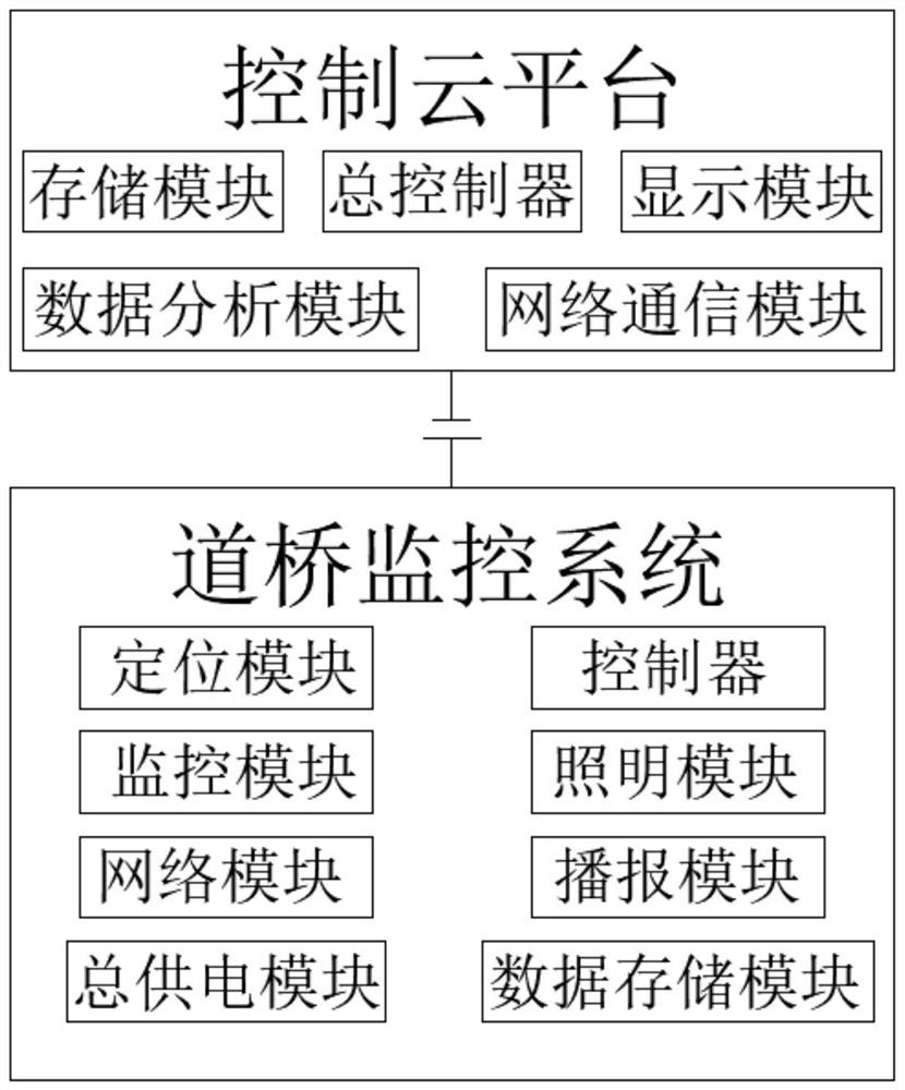
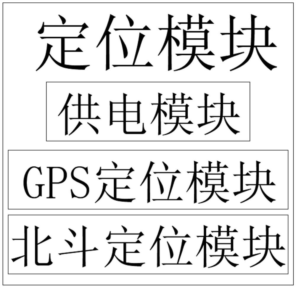
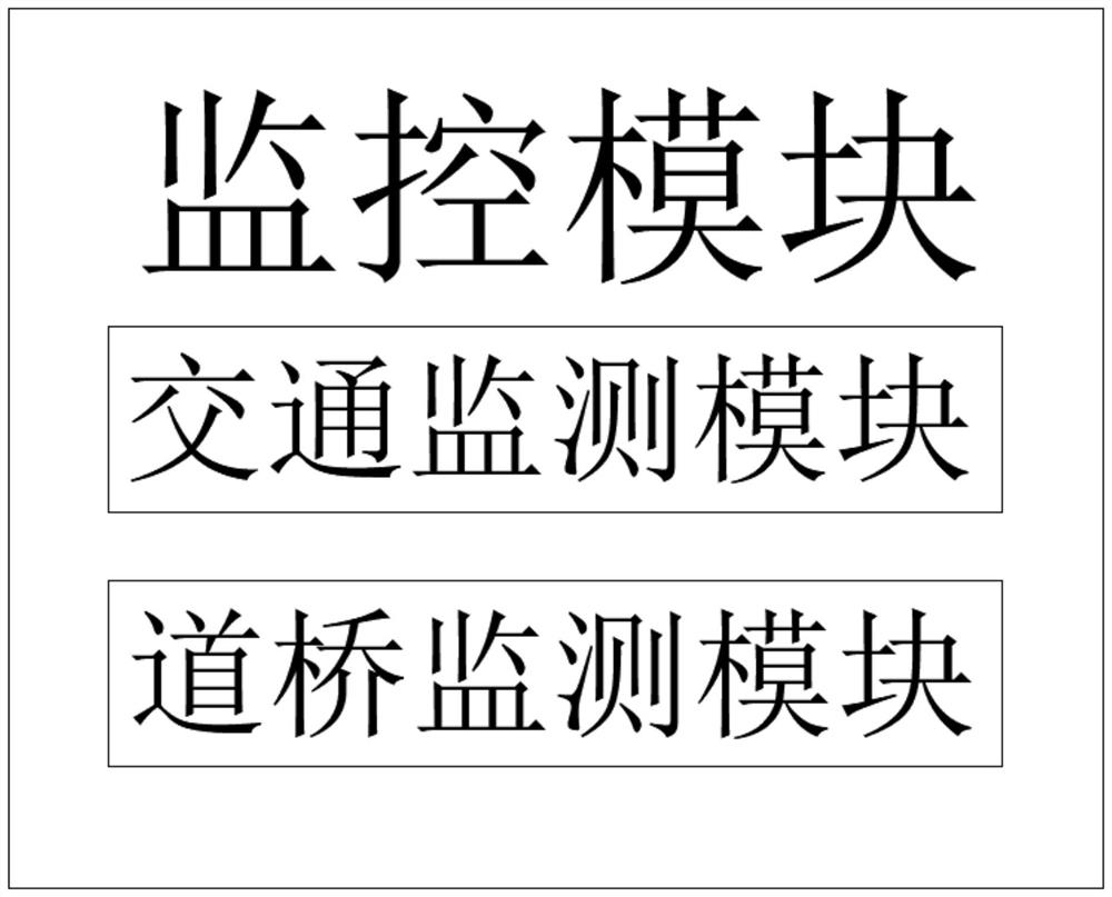
[0039] Such as Figure 1-9 As shown, the embodiment of the present invention provides an automated road and bridge control system, including a control cloud platform and a road and bridge monitoring system. The control cloud platform includes a storage module, a general controller, a display module, a data analysis module and a network analysis module, and the road and bridge monitoring system Including positioning module, controller, monitoring module, lighting module, broadcast module, total power supply module, network module and data storage module, the total controller is connected to the controller through the network module. The total power supply module includes the total battery, current stabilizer, city power supply , solar panel and power supply module, the power supply module includes a sub-battery and a charger, the solar panel and the city power supply are connected to the current stabilizer through wires, the current stabilizer is connected to the main battery th...

Embodiment 2

[0047] Such as Figure 1-9 As shown, the embodiment of the present invention provides an automatic road and bridge control method, the steps are as follows:

[0048] S1. When building a road and bridge, install the positioning module, monitoring module, lighting module, network module and broadcast module evenly on the main body of the road and bridge, and number each module and sensor through the labeling module. At the same time, the position of each module and sensor is determined by the positioning module, and the position information is stored in the data storage module and the storage module;

[0049] S2. LED street lights are evenly installed on both sides of roads and bridges, and the numbering module is used to number the LED street lights. The time relay is used to control the LED street lights to turn on at night and turn off during the day. When the season changes and the time of day and night changes, the controller communicates through the network The module cha...


PUM


Abstract

The invention provides an automatic road and bridge control method and system, and relates to the field of municipal engineering. The automatic road and bridge control method and system comprise a control cloud platform and a road and bridge monitoring system, and are characterized in that the control cloud platform comprises a storage module, a master controller, a display module, a data analysismodule and a network analysis module; and the road and bridge monitoring system comprises a positioning module, a controller, a monitoring module, a lighting module, a broadcasting module, a main power supply module, a network module and a data storage module, wherein the main controller is connected with the controller through the network module. The controller is supervised by the master controller, and then each module of the road and bridge monitoring system is controlled by the controller, so that the control of the system is simpler and clearer, a wireless network covering the whole road and bridge is formed by a routing module, and each module of the system is closely connected together by matching with a network communication module of each module, so that the management of workers is more convenient, and the method and system are worthy of vigorous promotion.

Description

technical field [0001] The invention relates to the technical field of municipal engineering, in particular to an automatic road and bridge control method and system. Background technique [0002] Daoqiao is the abbreviation of road and bridge, which belongs to the field of municipal engineering technology. Municipal engineering refers to the construction of municipal facilities. Various buildings, structures, equipment, etc., or free public products and services, and various public infrastructure constructions supporting urban life belong to the category of municipal engineering, such as common urban roads, bridges, subways, such as various closely related to life Various pipelines: rainwater, sewage, water supply, reclaimed water, electricity, telecommunications, heat, gas, etc., as well as the construction of squares and urban greening, etc., all belong to the category of municipal engineering. [0003] When the existing urban roads and bridges have problems, they cannot...

Claims


Application Information

Patent Timeline
Patent Type & Authority Applications(China)
IPC IPC(8): G05B19/418G01D21/02G01M5/00G08G1/052H04N7/18H05B45/10H05B47/16
CPCG01D21/02G01M5/0008G05B19/4183G05B19/4185G08G1/052H04N7/18H05B45/10H05B47/16Y02B20/30Y02B20/40
Inventor 郭朋朋张倩张艳艳贾彦丽张艳华
Owner HENAN VOCATIONAL & TECHN COLLEGE OF COMM
Learn More