Vital sign detection device, method and system
A technology for vital signs and detection devices, applied in the information field, can solve the problems of low wearing comfort and frequent charging, and achieve the effect of high detection accuracy
- Summary
- Abstract
- Description
- Claims
- Application Information
AI Technical Summary
Problems solved by technology
Method used
Image

Examples
Embodiment 1
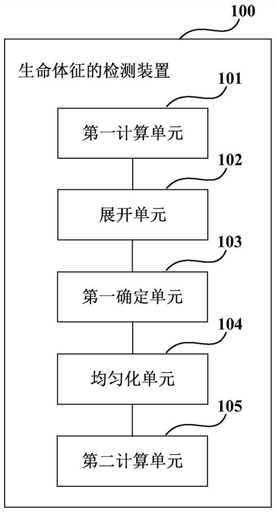
[0033] This embodiment provides a detection device for vital signs, figure 1 It is a schematic diagram of the vital sign detection device according to Embodiment 1 of the present invention. like figure 1 As shown, the vital sign detection device 100 includes:
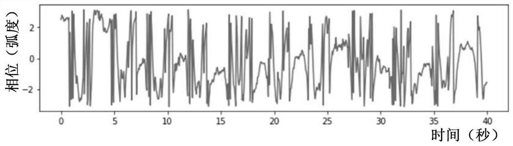
[0034] A first calculating unit 101, which is used to calculate the time-varying phase distribution of the distance Fast Fourier Transform (FFT) signal of the position of the living body according to the reflection signal of the microwave radar within the first preset time range;
[0035] Unfolding unit 102, which is used for phase unwrapping the phase distribution;
[0036] The first determination unit 103 is configured to determine all local extremum points of the phase distribution after phase unwrapping according to a preset time window, and the time window is determined according to the cycle range of the breathing or heartbeat of the living body;
[0037] A homogenization unit 104, which is used to homogenize t...
Embodiment 2
[0102] The embodiment of the present invention also provides an electronic device, Figure 13 It is a schematic diagram of the electronic device of Embodiment 2 of the present invention. like Figure 13 As shown, the electronic device 1300 includes a vital sign detection device 1301, wherein the structure and function of the vital sign detection device 1301 are the same as those described in Embodiment 1, and will not be repeated here.
[0103] Figure 14 It is a schematic block diagram of the system configuration of the electronic device according to Embodiment 2 of the present invention. like Figure 14 As shown, the electronic device 1400 may include a central processing unit 1401 and a memory 1402; the memory 1402 is coupled to the central processing unit 1401. This diagram is exemplary; other types of structures may also be used, in addition to or in place of this structure, for telecommunications or other functions.
[0104] like Figure 14 As shown, the electronic...
Embodiment 3
[0118] The embodiment of the present invention also provides a vital sign detection system, which includes a microwave radar and a vital sign detection device. The structure and function of the vital sign detection device are the same as those described in Embodiment 1, and the specific content will not be repeated. illustrate.
[0119] Figure 15 It is a schematic diagram of the detection system of vital signs in Embodiment 3 of the present invention, such as Figure 15 As shown, the vital sign detection system 1500 includes:
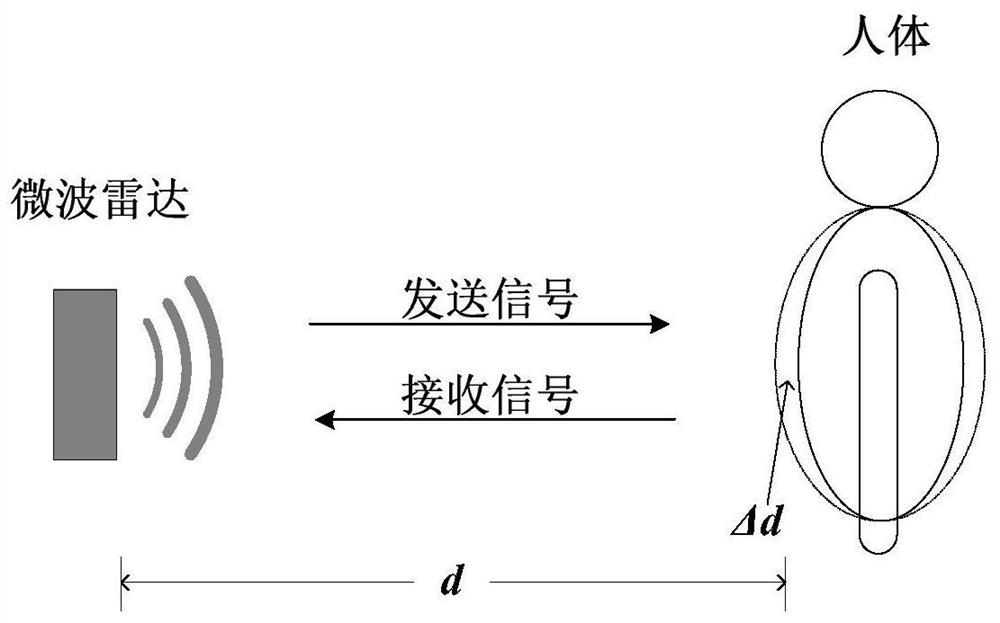
[0120] Microwave radar 1510, which has a signal transmitting unit 1511 and a signal receiving unit 1512, the signal transmitting unit 1511 transmits microwave signals to the space where the living body is located, and the signal receiving unit 1512 receives the reflected signal; and
[0121] The vital sign detecting device 1520 detects the vital sign according to the reflected signal.
[0122] For example, microwave radar 1510 is a microwave radar w...
PUM
 Abstract
Description
Claims
Application Information
 - R&D
- Intellectual Property
- Life Sciences
- Materials
- Tech Scout
- Unparalleled Data Quality
- Higher Quality Content
- 60% Fewer Hallucinations
Browse by: Latest US Patents, China's latest patents, Technical Efficacy Thesaurus, Application Domain, Technology Topic, Popular Technical Reports.
© 2025 PatSnap. All rights reserved.Legal|Privacy policy|Modern Slavery Act Transparency Statement|Sitemap|About US| Contact US: help@patsnap.com