A Dual-beam Frequency Scanning Leaky-Wave Antenna

A technology of frequency scanning and leaky wave antennas, which is applied to leaky waveguide antennas, antennas, electrical components, etc., can solve the problems of occupying too many spectrum resources, design difficulties, and cost increases, so as to improve radiation efficiency, suppress bandgap effects, The effect of simple structure

Active Publication Date: 2022-07-29
EAST CHINA NORMAL UNIV
View PDF0 Cites 0 Cited by
  • Summary
  • Abstract
  • Description
  • Claims
  • Application Information

AI Technical Summary

Problems solved by technology

The periodic leaky-wave antenna is a type of antenna that excites high-order harmonics for radiation. Because the traditional periodic leaky-wave antenna has problems such as narrow scanning angle and large bandwidth, it is difficult to realize dual-beam scanning. Therefore, how to realize a wide range and narrow bandwidth Dual-beam frequency-scanning antenna has become a focus of leaky-wave antenna design
[0003] The most common way to increase the scanning range is to increase the scanning frequency range, but this will bring relatively large bandwidth and occupy too much spectrum resources
In addition, in order to achieve dual-beam radiation, the traditional method is to use the common radiation of -1 and -2 harmonics to achieve dual beams, or to integrate two antennas with different radiation directions to achieve dual beams, but this It will bring design difficulties, complex structure, cost increase and other problems

Method used


Image

  • A Dual-beam Frequency Scanning Leaky-Wave Antenna
  • A Dual-beam Frequency Scanning Leaky-Wave Antenna
  • A Dual-beam Frequency Scanning Leaky-Wave Antenna

Examples


Embodiment

[0041] In order to describe the technical content, achieved objects and effects of the present invention in detail, the following descriptions are given with reference to the embodiments and the accompanying drawings.

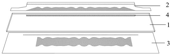
[0042] see figure 1 In this embodiment of the present invention, a dielectric substrate 1 is provided, and the top and bottom of the dielectric substrate 1 are respectively covered with metal panels.

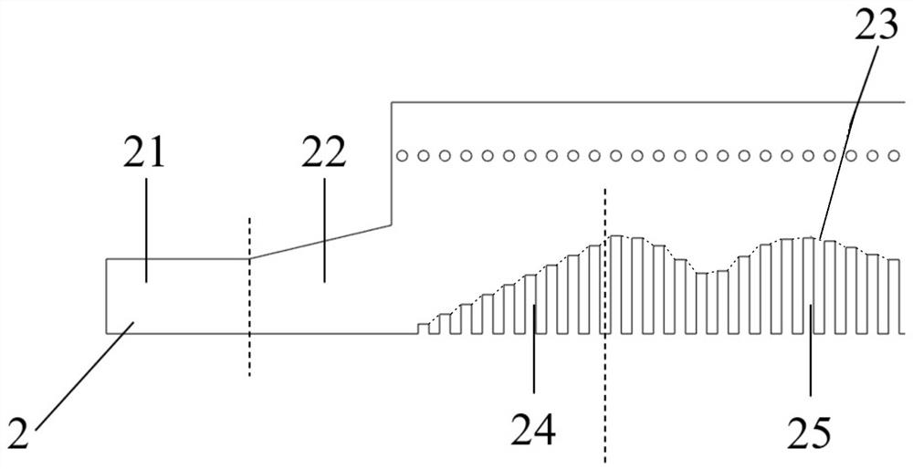
[0043] see figure 1 , figure 2 , the two ends of the top metal panel 2 are rectangular microstrip feed lines 21 connected to the trapezoidal impedance matching microstrip line 22, the semi-cloud-shaped impedance modulation area 23 set on the top metal panel 2 is divided into two parts, and the second part 25 is located in In the middle, the long grooves on it are double-period sinusoidal impedance modulation grooves whose etching height changes periodically; the first part 24 is located at both ends, and the long grooves on it are impedance matching grooves wh...


PUM


Abstract

The invention discloses a double-beam frequency scanning leaky wave antenna. The invention consists of a dielectric substrate, a top metal panel, a bottom metal panel and a metal tube; the invention adopts a half-mode substrate integrated waveguide structure and is based on the principle of periodic sinusoidal impedance modulation , set a dual-period sinusoidal impedance modulation slot on the top metal panel, as a radiation unit, since the top metal panel is formed by superimposing the sinusoidal impedances of two single beams, it can generate beams in two radiation directions; the same set on the bottom metal panel As a radiating unit, the periodically changing slot can not only improve the radiation efficiency of the antenna, but also suppress the stop-band effect of the periodic leaky-wave antenna. Compared with the traditional dual-beam frequency scanning antenna, the present invention has the advantages of simple structure, narrow bandwidth and large scanning angle. Features.

Description

technical field [0001] The invention relates to the technical fields of microwave, wireless communication and test simulation, in particular to a dual-beam frequency scanning leaky wave antenna based on periodic sinusoidal impedance modulation. Background technique [0002] Leaky wave antenna is a kind of traveling wave antenna with simple structure, frequency scanning ability and excellent directivity. It has been widely used in radar, aerospace and other fields. Since the invention of leaky-wave antennas, the technology has been very mature so far, which can be divided into the following four categories: uniform, quasi-uniform, periodic, and left-handed composite leaky-wave antennas. Periodic leaky wave antenna is a type of antenna that excites higher harmonics for radiation. Due to the narrow scanning angle and large bandwidth of traditional periodic leaky wave antenna, it is difficult to achieve dual beam scanning. The dual-beam frequency scanning antenna has become a k...

Claims


Application Information

Patent Timeline
Patent Type & Authority Patents(China)
IPC IPC(8): H01Q1/36H01Q13/20H01Q13/08
CPCH01Q1/36H01Q13/20H01Q13/08
Inventor 彭臻翟国华丁军高建军
Owner EAST CHINA NORMAL UNIV
Why Eureka
Try Eureka