
A cavity structure capable of reducing drag in internal flow and scramjet engine

A scramjet and engine technology, which is applied in the combustion chamber, combustion method, combustion equipment, etc., can solve the problems of large total pressure loss, large negative thrust on the wall of the rear edge of the cavity, and the pressure distribution of the internal flow characteristics of the engine is not considered. To achieve the effect of reducing internal resistance and reducing flow loss

Active Publication Date: 2022-04-22
NAT UNIV OF DEFENSE TECH
View PDF0 Cites 0 Cited by
  • Summary
  • Abstract
  • Description
  • Claims
  • Application Information

AI Technical Summary

Problems solved by technology

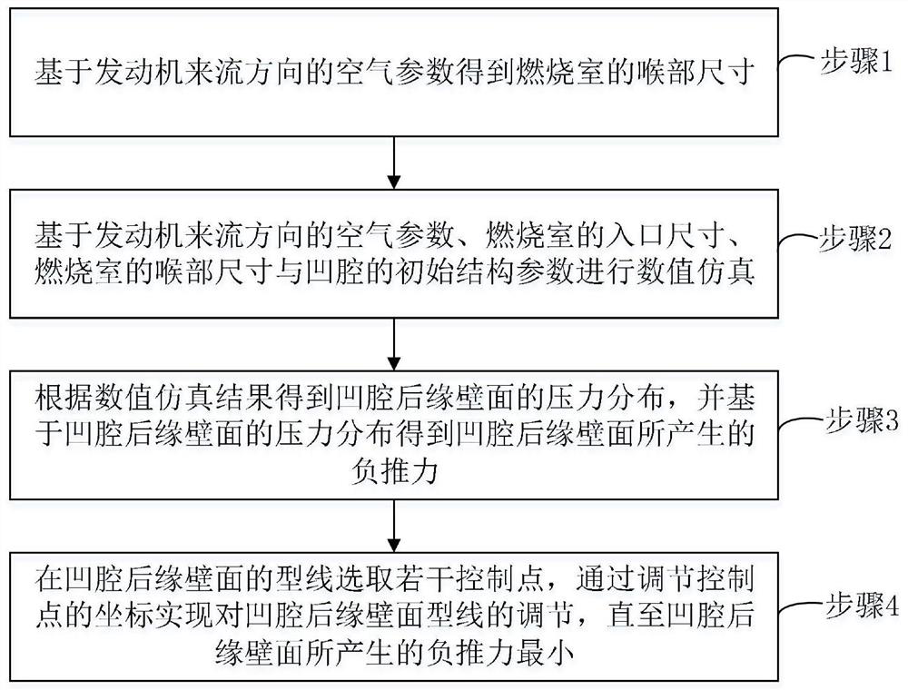
[0004] However, the existing wall design of the rear edge of the concave cavity does not consider the internal flow characteristics of the engine and the pressure distribution in the cavity, and strong shock waves will be introduced into the flow channel, resulting in a large total pressure loss. The negative thrust generated is still large

Method used


Image

  • A cavity structure capable of reducing drag in internal flow and scramjet engine
  • A cavity structure capable of reducing drag in internal flow and scramjet engine
  • A cavity structure capable of reducing drag in internal flow and scramjet engine

Examples


Embodiment Construction

[0035] The following will clearly and completely describe the technical solutions in the embodiments of the present invention with reference to the accompanying drawings in the embodiments of the present invention. Obviously, the described embodiments are only part of the embodiments of the present invention, not all of them. Based on the embodiments of the present invention, all other embodiments obtained by persons of ordinary skill in the art without creative efforts fall within the protection scope of the present invention.

[0036] It should be noted that all directional indications (such as up, down, left, right, front, back...) in the embodiments of the present invention are only used to explain the relationship between the components in a certain posture (as shown in the accompanying drawings). Relative positional relationship, movement conditions, etc., if the specific posture changes, the directional indication will also change accordingly.

[0037] In addition, in t...


PUM


Abstract

The invention discloses a cavity structure capable of internal flow and drag reduction and a scramjet engine. The cavity structure includes a cavity front wall surface, a cavity bottom wall surface and a cavity rear edge wall surface, the cavity front edge wall surface, The bottom wall of the concave cavity and the rear edge wall of the concave cavity are connected in sequence and arranged on the wall of the combustion chamber along the direction of the incoming flow of the engine. It is smoothly connected with the bottom wall of the concave cavity and the wall of the combustion chamber. The concave cavity structure optimizes the concave cavity rear edge curved wall structure based on the flow field structure and pressure distribution in the concave cavity, which can not only optimize the negative thrust distribution on the concave cavity rear edge wall, effectively reduce the internal resistance of the engine, but also weaken the transonic shock wave , effectively reduce the internal flow loss of the engine, and at the same time, due to the smooth transition of the wall of the rear edge of the cavity, the thermal stress on the wall of the rear edge of the cavity is concentrated, and the existing active cooling thermal protection and passive thermal protection technologies can be well applied.

Description

technical field [0001] The invention relates to the technical field of engines, in particular to a cavity structure capable of internal flow and drag reduction and a scramjet engine. Background technique [0002] Hypersonic aircraft is a strategic high-tech that can achieve high-speed defense penetration, 2-hour global reach, and low-cost space entry. Its development will change the shape of future warfare. pose a new threat to our national security. As the best alternative power plant for hypersonic air-breathing flight, the scramjet has become a research hotspot in various aerospace powers. As the core component of the scramjet engine, the performance of the supersonic combustion chamber directly determines the success or failure of the entire engine development. Due to the high incoming flow velocity and short residence time, the successful design of a supersonic combustor must rely on reliable flame stabilization technology. The wall cavity can effectively stabilize t...

Claims


Application Information

Patent Timeline
Patent Type & Authority Patents(China)
IPC IPC(8): F23R3/42G06F30/20G06F119/14
CPCF23R3/42G06F30/20G06F2119/14
Inventor 孙明波王前程杨揖心蔡尊赵国焱
Owner NAT UNIV OF DEFENSE TECH
Learn More