Full-automatic combination machine for processing crankshaft of engine

A crankshaft processing, fully automatic technology, applied in metal processing equipment, grinding machine parts, manufacturing tools, etc., can solve the problems of reducing friction, inconvenient grinding, and reducing production grinding efficiency, so as to improve grinding efficiency and practicality performance effect

Inactive Publication Date: 2021-03-02
芜湖肯昌机电有限公司
View PDF0 Cites 0 Cited by
  • Summary
  • Abstract
  • Description
  • Claims
  • Application Information

AI Technical Summary

Problems solved by technology

It bears the force transmitted from the connecting rod, converts it into torque and outputs it through the crankshaft and drives other accessories on the engine to work. Under the action of bending torsional load, the outer wall of the crankshaft needs to be polished during production and processing, so as to reduce the friction force generated when it works and rotate, thereby reducing the probability of cylinder explosion. Since the crankshaft has a certain curved shape, When it rotates, its outer wall is rotating while rotating, so it is not convenient to grind it, thereby reducing the efficiency of its production and grinding

Method used


Image

  • Full-automatic combination machine for processing crankshaft of engine
  • Full-automatic combination machine for processing crankshaft of engine
  • Full-automatic combination machine for processing crankshaft of engine

Examples


Embodiment Construction

[0021] The following will clearly and completely describe the technical solutions in the embodiments of the present invention with reference to the accompanying drawings in the embodiments of the present invention. Obviously, the described embodiments are only some, not all, embodiments of the present invention. Based on the embodiments of the present invention, all other embodiments obtained by persons of ordinary skill in the art without making creative efforts belong to the protection scope of the present invention.

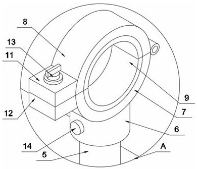
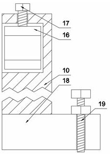
[0022] The present invention provides such as Figure 1-5 A fully automatic combined machine for machining crankshafts of generators is shown, including a processing table 1, a positioning block 2 is symmetrically fixedly connected to the top of the processing table 1, and a bearing plate 3 is slidably connected between the two positioning blocks 2, carrying Both the middle part of the upper surface and the middle part of the lower surface of the board 3 are r...


PUM


Abstract

The invention discloses a full-automatic combination machine for processing a crankshaft of an engine. The full-automatic combination machine comprises a processing table, positioning blocks are symmetrically and fixedly connected to the top of the processing table, a bearing plate is connected between two positioning blocks in a sliding manner, a ball body is rotationally embedded in the bearingplate, a first connecting rod is fixedly connected to the top of one ball body, the top of the outer wall of the first connecting rod is sleeved with a connecting sleeve in a sliding manner, a first arc plate is fixedly connected to the top of the connecting sleeve, a second arc plate is rotationally connected to the top of the first arc plate, polishing plates are fixedly connected to one sides,opposite to each other, of the first arc plate and the second arc plate correspondingly, and supporting columns are arranged on two sides of the top of the processing table. By using the arrangement way of the first arc plate and the second arc plate, a ring can be formed by the first arc plate and the second arc plate, and sleeves the outer wall of the crankshaft, and the crankshaft rotates alongwith the ring when the ring rotates, so that the polishing plates polish the crankshaft, which improves the crankshaft polishing efficiency.

Description

technical field [0001] The invention relates to the field of generator crankshafts, in particular to a fully automatic combined machine for machining generator crankshafts. Background technique [0002] The crankshaft is the most important component in the engine. It bears the force transmitted from the connecting rod, converts it into torque and outputs it through the crankshaft and drives other accessories on the engine to work. Under the action of bending torsional load, the outer wall of the crankshaft needs to be polished during production and processing, so as to reduce the friction force generated when it works and rotate, thereby reducing the probability of cylinder explosion. Since the crankshaft has a certain curved shape, When it rotates, its outer wall is turning around while rotating, so it is not convenient to polish it, and then reduce the efficiency of its production and polishing. Contents of the invention [0003] The object of the present invention...

Claims


Application Information

Patent Timeline
Patent Type & Authority Applications(China)
IPC IPC(8): B24B5/42B24B41/06B24B27/02B24B41/04B24B5/35B24B47/12
CPCB24B5/355B24B5/42B24B5/421B24B27/02B24B41/04B24B47/12
Inventor 李凌云
Owner 芜湖肯昌机电有限公司
Why Eureka
Try Eureka