Display screen assembling, locking and carrying device and method

A technology of handling device and display screen, applied in the field of display screen, can solve the problems of wear of screw bit rod, cumbersome disassembly steps, unfavorable protection of display screen end cover, etc., to achieve the effect of improving replacement efficiency and increasing covering area

Inactive Publication Date: 2021-03-02
田丽玖
View PDF1 Cites 1 Cited by
  • Summary
  • Abstract
  • Description
  • Claims
  • Application Information

AI Technical Summary

Problems solved by technology

[0004] The prior art has the following deficiencies: 1. When positioning the display screen end cover, first fix the display screen end cover positioning jig with screws on the jig handling mechanism; then place the display screen end cover in the positioning jig Positioning; finally use the jig pressing assembly to press the edge of the display end cover to complete the positioning process; when fixing the positioning jig with screws, each screw of the positioning jig needs to be tightened when installing and disassembling the positioning jig Or loosen; when the positioning fixture needs to be replaced frequently due to the processing of various display screen end covers, the disassembly steps will be cumbersome due to the removal of more screws, thereby reducing the efficiency of positioning fixture replacement
At the same time, when the fixture pressing component presses the end cover of the display screen, it only compresses the end cover of the display screen; when there are many impurities in the processing environment, the part of the end cover of the display screen that is not pressed and covered is easily covered by dust, etc. Covered by impurities, which is not conducive to the protection of the display screen end cover processing
2. When tightening the screws of the end cover of the display screen, the screw slider is fixed on the positioning bottom plate, and the screw feeding mechanism feeds the screw to the corresponding hole of the positioning chuck along the inner feeding channel of the screw slider to position the screw; then The tightening machine drives the screw bit through the inner hole of the positioning bottom plate to move down to the position of the screw in the positioning chuck, drives the screw to move down to stretch the positioning chuck, and then tightens the screw into the screw hole of the display screen end cover; and the screw slider It is fixedly connected with the positioning bottom plate, that is, the screw feeding channel inside the screw slider is always connected with the downward movement channel of the screw batch head in the positioning bottom plate; when the screw feeding mechanism feeds multiple screws at a time due to feeding reasons, only one screw falls. Insert the position of the screw in the positioning chuck, and the remaining screws are stuck in the screw feeding channel inside the screw slider; when the tightening machine drives the screw bit through the hole in the positioning bottom plate that communicates with the screw feeding channel, it moves down to the positioning chuck When the position of the screw drives the screw to move down, the screw bit rod will contact and rub against the remaining screws in the screw feeding channel; thus causing the wear of the screw bit rod, or even jamming the screw bit rod and causing the screw bit rod to break when it moves down At the same time, the remaining screws in the screw feeding channel cannot be discharged in time, and the next screw feeding will cause more than one screw to be fed; that is, there is always friction between the redundant screws and the screw bit rod in the screw feeding channel , thereby reducing the service life of the screw bit rod

Method used


Image

  • Display screen assembling, locking and carrying device and method
  • Display screen assembling, locking and carrying device and method
  • Display screen assembling, locking and carrying device and method

Examples


Embodiment 1

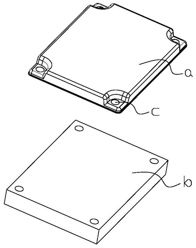
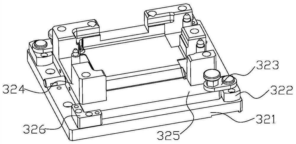
[0027] Such as figure 1 The shown locking transport device 1 includes a jig transport mechanism 3 and a locking mechanism 4; both the jig transport mechanism 3 and the locking mechanism 4 are fixed on the workbench; the input end and the output end of the jig transport mechanism 3 They are respectively connected with the feed port of the end cover of the display screen and the input end of the moving detection device, and the input end of the fixture handling mechanism 3 is matched with the end cover of the display screen; the output ends of multiple locking mechanisms 4 are respectively connected with the screw holes of the end cover of the display screen The fixture transport mechanism 3 is used to position and transport the end cover of the display screen; the locking mechanism 4 is used to lock a plurality of screws respectively on the screw holes of the end cover of the display screen.

[0028] The product flow direction of the end cover of the display screen is: the jig ...


PUM


Abstract

The invention relates to the field of display screens, in particular to a display screen assembling, locking and carrying device and method. The device comprises a jig carrying mechanism and locking mechanisms. The input end and the output end of the jig carrying mechanism are connected with a display screen end cover feed port and the input end of a carrying detection device correspondingly. Theoutput ends of the multiple locking mechanisms are connected with display screen end cover screw holes correspondingly. The jig carrying mechanism is used for positioning and carrying display screen end covers. The locking mechanisms are used for locking multiple screws into the display screen end cover screw holes correspondingly. By means of the device, by arranging the jig carrying mechanism, the replacement efficiency of a positioning jig is improved, and the display screen end covers are prevented from being covered with dust and other impurities; and by arranging the locking mechanisms,wear of screwdriver bit rods is reduced, and the service life of the screwdriver bit rods is prolonged.

Description

technical field [0001] The invention relates to the field of display screens, in particular to a device and method for assembling, locking and transporting a display screen. Background technique [0002] The display screen is a display tool that displays a certain electronic file on the screen through a specific transmission device and then reflects it to the human eye. According to the different manufacturing materials, it can be divided into: cathode ray tube display, plasma display, liquid crystal display and so on. The display screen includes a display screen end cover and a display screen shell. Various electrical components are installed inside the display screen shell. The display screen end cover is connected to the rear side of the display screen shell by a plurality of screws to fasten and seal it. The screw connection between the display screen end cover and the display case has an important influence on the performance of the display screen. Whether the screw c...

Claims


Application Information

Patent Timeline
Patent Type & Authority Applications(China)
IPC IPC(8): B23P19/00B23P19/06
CPCB23P19/001B23P19/06
Inventor 田丽玖吴杰
Owner 田丽玖
Why Eureka
Try Eureka