
Ultrasonic amplitude-change pole with frequency modulation sucker

A horn and ultrasonic technology, applied in the direction of magnetic attraction or thrust holding device, fluid using vibration, electrical components, etc., can solve problems such as difficult to achieve stable frequency modulation, achieve ingenious design, solve stable frequency modulation, and reasonable structure Effect

Active Publication Date: 2021-03-02
ZHONGBEI UNIV
View PDF5 Cites 2 Cited by
  • Summary
  • Abstract
  • Description
  • Claims
  • Application Information

AI Technical Summary

Problems solved by technology

[0003] In order to solve the problem that the traditional ultrasonic horn frequency modulation technology is difficult to achieve stable frequency modulation, the present invention provides an ultrasonic horn with a frequency modulation suction cup

Method used


Image

  • Ultrasonic amplitude-change pole with frequency modulation sucker
  • Ultrasonic amplitude-change pole with frequency modulation sucker
  • Ultrasonic amplitude-change pole with frequency modulation sucker

Examples


Embodiment Construction

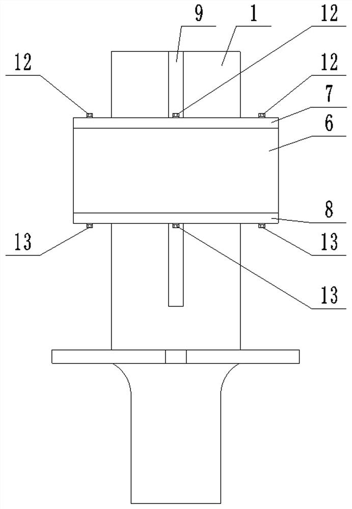
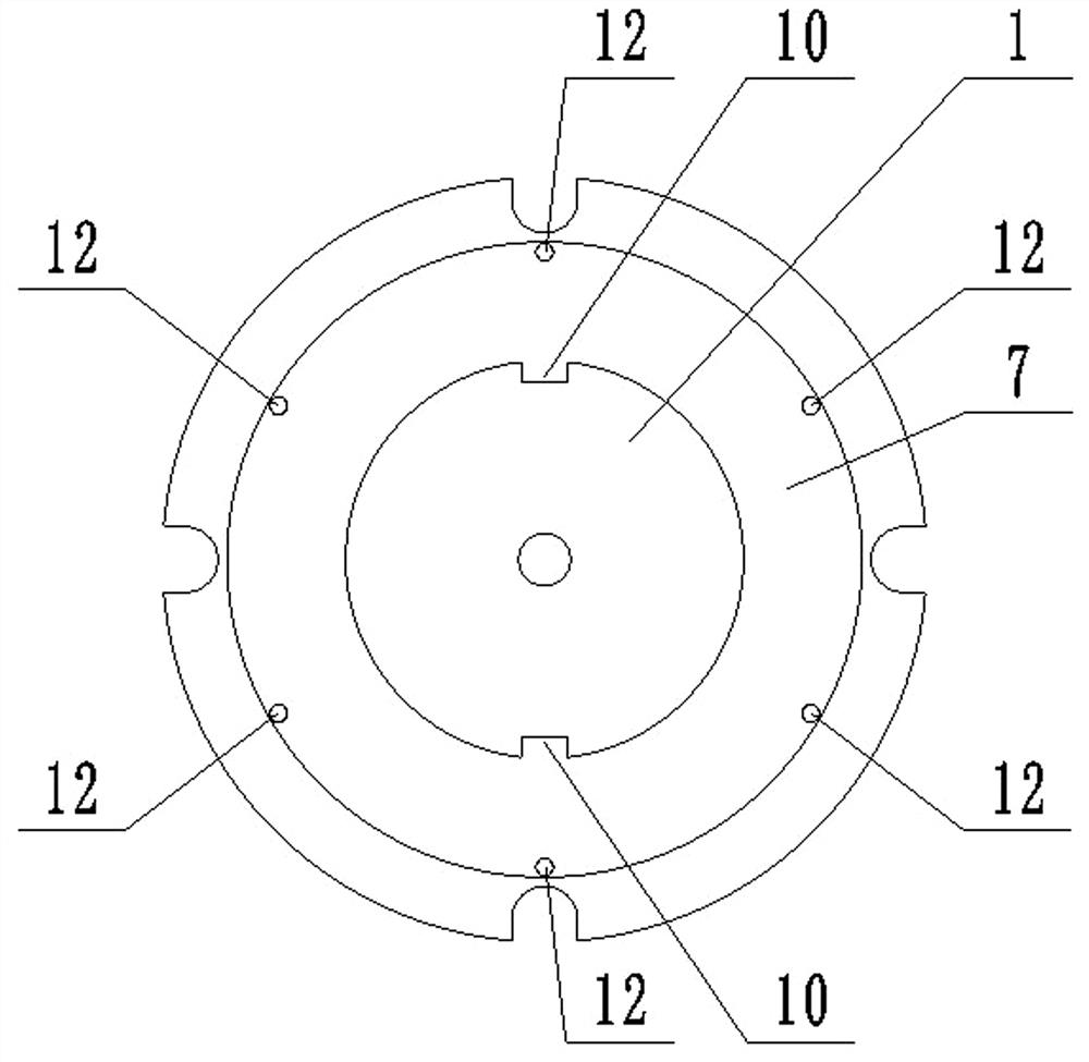
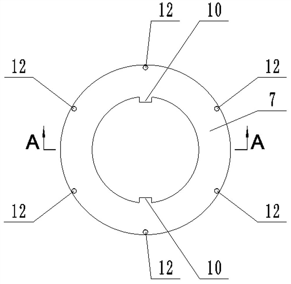
[0021] An ultrasonic horn with a frequency-modulating suction cup includes an ultrasonic horn body 1 and a frequency-modulating sucker; the frequency-modulating sucker includes a cylindrical magnetic sleeve 2, a cylindrical yoke 3, and M arc-groove permanent magnets 4. M arc-groove electromagnets 5, a cylindrical shell 6, an annular top cover 7, and an annular bottom cover 8; M is a positive integer, and M≥2;

[0022] Wherein, the cylindrical section of the ultrasonic horn body 1 faces upward, and the side of the cylindrical section of the ultrasonic horn body 1 is provided with two mutually symmetrical guide grooves 9 along the axial direction; the lower ends of the two guide grooves 9 are closed , the upper end of which passes through the upper end surface of the cylindrical section of the ultrasonic horn body 1;

[0023] The cylindrical magnetic sleeve 2 is coaxially sleeved on the side of the cylindrical section of the ultrasonic horn body 1; the cylindrical yoke 3 is coax...


PUM


Abstract

The invention relates to an ultrasonic amplitude-change pole, in particular to an ultrasonic amplitude-change pole with a frequency modulation sucker. The problem that stable frequency modulation is difficult to achieve through a traditional ultrasonic amplitude-change pole frequency modulation technology is solved. The ultrasonic amplitude-change pole with the frequency modulation sucker comprises an ultrasonic amplitude-change pole body and further comprises the frequency modulation sucker. The frequency modulation sucker comprises a cylindrical magnetic conductive sleeve, a cylindrical yoke, M arc-groove-shaped permanent magnets, M arc-groove-shaped electromagnets, a cylindrical shell, a circular-ring-shaped top cover and a circular-ring-shaped bottom cover, and M is a positive integerand is greater than or equal to 2, wherein a cylindrical section of the ultrasonic amplitude-change pole body faces upwards, and two symmetrical guide grooves are formed in the side face of the cylindrical section of the ultrasonic amplitude-change pole body in the axial direction; and the lower ends of the two guide grooves are closed, and the upper ends of the two guide grooves penetrate throughthe upper end face of the cylindrical section of the ultrasonic amplitude-change pole body. The ultrasonic amplitude-change pole is suitable for ultrasonic machining.

Description

technical field [0001] The invention relates to an ultrasonic horn, in particular to an ultrasonic horn with a frequency modulation suction cup. Background technique [0002] Ultrasonic horn is an important equipment in ultrasonic machining. Its main function is to amplify the ultrasonic mechanical vibration generated by the ultrasonic transducer and transmit it to the tool. In the actual processing process, when the processing conditions (such as the size and quality of the tool, the material of the workpiece, etc.) change, the natural frequency of the ultrasonic horn will not adapt to the processing conditions, thus affecting the processing quality and processing efficiency. At this time, in order to ensure the processing quality and processing efficiency, it is necessary to frequency-modulate the ultrasonic horn (that is, adjust the natural frequency of the ultrasonic horn), so that the natural frequency of the ultrasonic horn can adapt to the processing conditions. The...

Claims


Application Information

Patent Timeline
IPC IPC(8): B06B1/04B06B3/00H02N15/00
CPCB06B1/045B06B3/00H02N15/00
Inventor 王建青邵延君崔学良祝锡晶傅迎泽潘振钊
Owner ZHONGBEI UNIV
Learn More