Hydraulic loading servo control system for output shaft of speed reducer and control method

A servo control system and hydraulic loading technology, which is applied in fluid pressure actuation system components, servo meter circuits, servo motor components, etc., can solve the problem that the oil temperature cannot be controlled within the working range, and the oil motor torque and speed control are inaccurate and other problems to achieve the effect of simple structure and preventing excessive pressure difference

Pending Publication Date: 2021-02-26
CHINA NON-FERROUS METALS PROCESSING TECH CO LTD
View PDF0 Cites 0 Cited by
  • Summary
  • Abstract
  • Description
  • Claims
  • Application Information

AI Technical Summary

Problems solved by technology

[0002] It is known that for the output shaft of the reducer, it is often necessary to carry out a load test. It is an efficient and economical way to use hydraulic drag loading. However, in the prior art, the control of the torque and speed of the oil motor is inaccurate, and the oil temperature Often cannot be controlled within the working range, therefore, to propose a precise control and adjustment of the torque and speed of the tested piece has become the basic appeal of those skilled in the art

Method used


Image

  • Hydraulic loading servo control system for output shaft of speed reducer and control method

Examples


Embodiment Construction

[0017] The present invention can be explained in detail through the following examples, and the purpose of disclosing the present invention is to protect all technical improvements within the scope of the present invention.

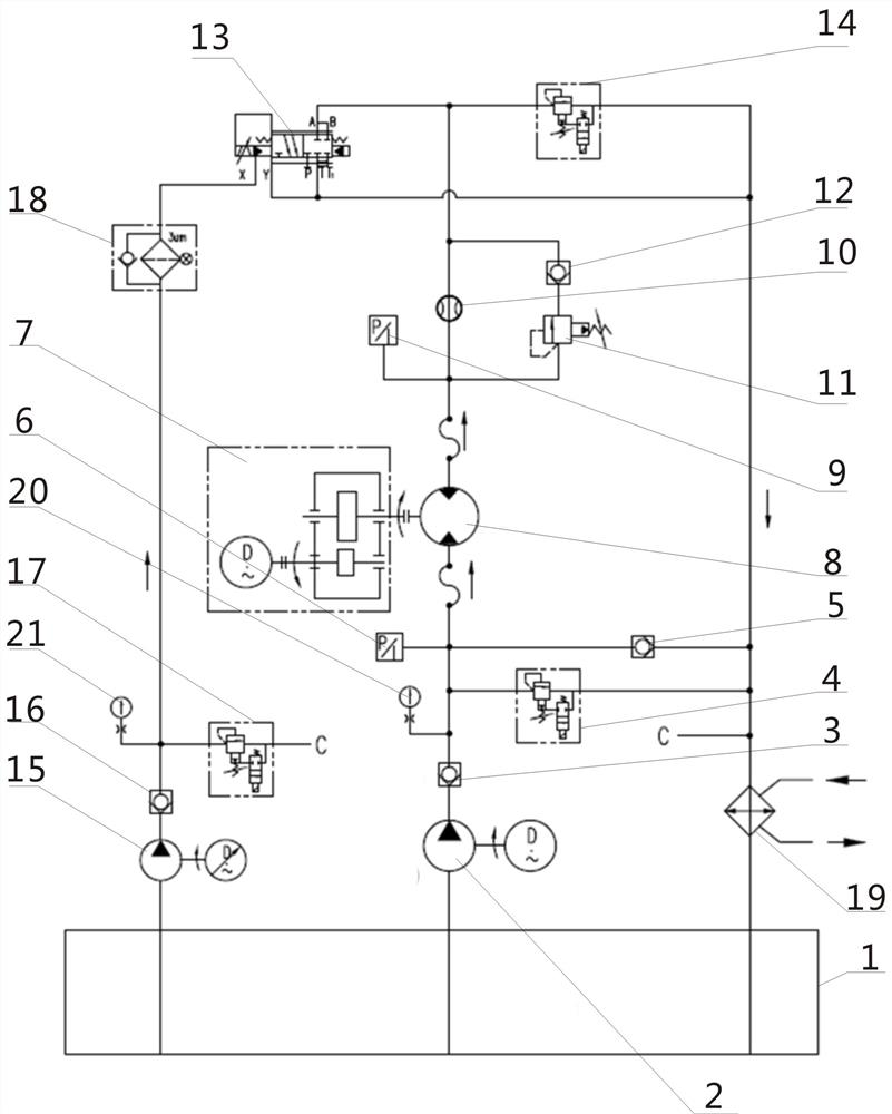
[0018] combined with figure 1 The hydraulically loaded servo control system for the output shaft of the reducer includes an oil tank 1, a pump motor unit A2, a pump motor unit B15, a test piece 7, an oil motor 8 and a cooler 19, a pump motor unit A2, and a pump motor unit B15 The oil inlets of the pumps are respectively connected to the oil tank 1, the outlet of the pump motor unit A2 is connected to the inlet of the oil motor 8 through the pipeline A, and the pipeline A is provided with a check valve A3, a pressure gauge A20 and a pressure sensor A6 in sequence, and the oil motor The output end of 8 is fixedly connected with test piece 7 through a coupling, the oil outlet of oil motor 8 is connected with the control oil port (A, B) of servo valve 13 thro...


PUM


Abstract

The invention provides a hydraulic loading servo control system for an output shaft of a speed reducer and a control method, and relates to the technical field of hydraulic control systems. The hydraulic loading servo control system comprises an oil tank, a pump motor set A, a pump motor set B, a testing piece, an oil motor and a cooler, wherein oil inlets of the pump motor set A and the pump motor set B are connected with the oil tank, an outlet of the pump motor set A is connected with an inlet of the oil motor through a pipeline A, a one-way valve A, a pressure gauge A and a pressure sensorA are sequentially arranged on the pipeline A, an output end of the oil motor is fixedly connected with the testing piece through a coupling, an oil outlet of the oil motor is connected with controloil ports (A, B) of a servo valve through a pipeline B, an oil return port (T) of the servo valve is connected with the cooler through a pipeline C, and an oil outlet of the cooler is connected into the oil tank. The hydraulic loading servo control system is simple in structure, realizes the accurate control and adjustment of the torque and the rotating speed of a to-be-tested piece.

Description

technical field [0001] The invention relates to the technical field of hydraulic control systems, in particular to a servo control system and control method for hydraulically loading an output shaft of a reducer. Background technique [0002] It is known that for the output shaft of the reducer, it is often necessary to carry out a load test. It is an efficient and economical way to use hydraulic drag loading. However, in the prior art, the control of the torque and speed of the oil motor is inaccurate, and the oil temperature Often cannot be controlled within the working range, therefore, to provide a precise control and adjustment of the torque and rotational speed of the tested piece has become the basic appeal of those skilled in the art. Contents of the invention [0003] In order to overcome the deficiencies in the background technology, the present invention discloses a servo control system and control method for hydraulically loading the output shaft of the reducer...

Claims


Application Information

Patent Timeline
Patent Type & Authority Applications(China)
IPC IPC(8): F15B13/02F15B21/041F15B21/0423G01M13/02
CPCF15B13/02F15B13/024F15B13/027F15B21/041F15B2211/20515F15B2211/6306F15B2211/632F15B2211/6656F15B21/0423G01M13/02
Inventor 张瑞虹马旭凯
Owner CHINA NON-FERROUS METALS PROCESSING TECH CO LTD
Why Eureka
Try Eureka