Cleaning device for spinneret plate machining

A technology of cleaning device and spinneret, applied in spinneret assembly, textile and papermaking, etc., can solve the problems of low cleaning efficiency, high cleaning cost, waste of resources, etc., and achieve the effect of high cleaning efficiency

Inactive Publication Date: 2021-02-26
JIANGSU BIAOLI PRECISION MACHINERY CO LTD
View PDF9 Cites 0 Cited by
  • Summary
  • Abstract
  • Description
  • Claims
  • Application Information

AI Technical Summary

Problems solved by technology

[0003] The cleaning equipment for blind hole spinneret cleaning in the industry has long been using the cleaning method of cleaning one side one by one. This cleaning method has disadvantages such as low cleaning efficiency, waste of resources, and high cleaning costs. Double-sided cleaning, high cleaning efficiency, clean cleaning device for spinneret processing

Method used


Image

  • Cleaning device for spinneret plate machining
  • Cleaning device for spinneret plate machining
  • Cleaning device for spinneret plate machining

Examples


Embodiment 1

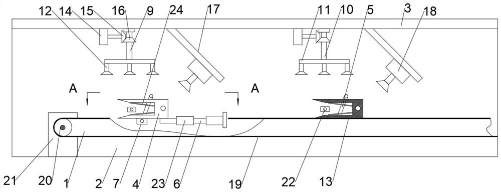
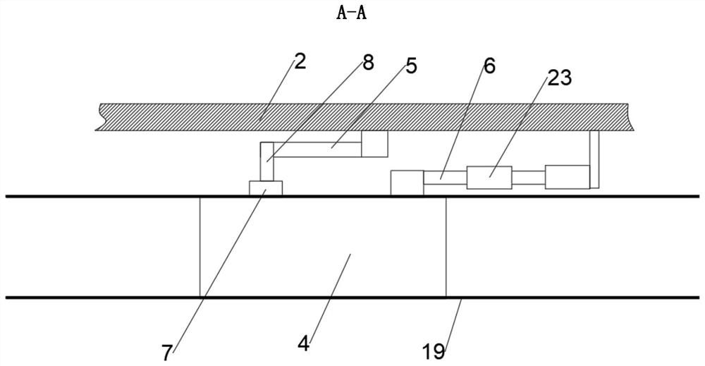
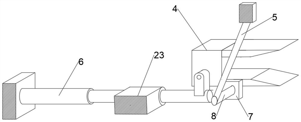
[0023] see Figure 1~4 , in an embodiment of the present invention, a cleaning device for spinneret processing, including a conveying device 1, a side wall 2, and a top wall 3, the side wall 2 is arranged on one side of the conveying device 1, and the top wall 3 is arranged on the Above the conveying device 1 and the top wall 3 is fixedly connected with the side wall 2. Two clamping and turning mechanisms 13 are fixed on the side wall 2. The clamping and turning mechanisms 13 include a clamp 4, a connecting rod 5, a hydraulic lifting and shrinking rod 6. Rotating base 7, rotating rod 8, guide rail 23, one side of the fixture 4 is fixedly connected with the rotating base 7, one end of the rotating rod 8 is rotationally connected with the rotating base 7 and the other end of the rotating rod 8 is rotationally connected with the connecting rod 5 , the connecting rod 5 is hinged on the side wall 2, one end of the hydraulic lift-contraction rod 6 is fixedly connected to the side wa...

Embodiment 2

[0030] see Figure 1~4 The difference between the embodiment of the present invention and embodiment 1 is that the two cleaning mechanisms 9 are provided with a rotating shaft 10, a rotating disk 11, and a nozzle 12, and the rotating shaft 10 is connected to the lower end surface of the top wall 3 in rotation and the rotating shaft 10 The lower end surface is fixedly connected with the turntable 11, and each cleaning mechanism 9 is provided with three nozzles 12 and the three nozzles 12 in each cleaning mechanism 9 are arranged at equal intervals along the circumference of the lower end surface of the turntable 11, and the lower end surfaces of the top wall 3 are respectively Two rotating motors 14 are fixedly connected, and the output shafts of the two rotating motors 14 are fixedly connected with a bevel gear I15, and the rotating shafts 10 in the two cleaning mechanisms 9 are provided with bevel gear II16 and bevel gear I15. Mesh transmission with bevel gear II16.

[0031]...


PUM


Abstract

The invention discloses a cleaning device for spinneret plate machining. The cleaning device comprises a conveying device, side walls and a top wall, two clamping turnover mechanisms are fixed to theside walls, each clamping turnover mechanism comprises a clamp, a connecting rod, a hydraulic telescopic rod, a rotating seat, a rotating rod and a guide rail, one side face of each clamp is fixedly connected with the corresponding rotating seat, one ends of the rotating rods are rotationally connected with the rotating seats, and the other ends of the rotating rods are rotationally connected withthe connecting rods; the connecting rods are hinged to the side walls, one ends of the hydraulic telescopic rods are fixedly connected with the side walls through supporting seats, the other ends ofthe hydraulic telescopic rods are hinged to the clamps, the guide rails are fixedly connected with the side walls, and the inner side walls of the guide rails are slidably connected with the hydraulictelescopic rods; and two cleaning mechanisms are arranged on the upper portions of the two clamping turnover mechanisms correspondingly, and the two cleaning mechanisms are both connected to the lower end face of the top wall. The cleaning device for spinneret plate machining is high in cleaning efficiency and thorough in cleaning.

Description

technical field [0001] The invention relates to the field of spinneret processing, in particular to a cleaning device for spinneret processing. Background technique [0002] The function of the spinneret is that the high polymer in the viscous flow state passes through the spinneret to become a fine fluid with a specific cross-section, and the fine fluid is stretched, condensed and solidified into a filament. , As a filament-forming element in chemical fiber spinning, it has a wide range of application values ​​in chemical fiber spinning. In the process of processing, firstly, pre-holes (commonly known as blind holes) that have not been drilled through are roughly machined on the board, and then micro-holes with smaller sizes are finely machined on this basis. Since the blind hole is an impenetrable deep hole, the iron filings and sundries (salad oil, etc.) during processing are easy to accumulate at the bottom of the hole, and this part of the hole and the bottom of the ho...

Claims


Application Information

Patent Timeline
Patent Type & Authority Applications(China)
IPC IPC(8): D01D4/04
CPCD01D4/04
Inventor 潘仁汉潘仁先秦正军
Owner JIANGSU BIAOLI PRECISION MACHINERY CO LTD
Why Eureka
Try Eureka