
A control strategy for electric drive dump truck braking system

A braking system and control strategy technology, applied in the direction of brakes, braking transmissions, vehicle components, etc., can solve the problems of increasing braking reaction time, increasing energy consumption, complex braking system, etc., to shorten the reaction time, increase the Service life, effect of simplified braking system

Active Publication Date: 2022-04-05
GUANGZHOU ELECTRICAL LOCOMOTIVE
View PDF6 Cites 0 Cited by
  • Summary
  • Abstract
  • Description
  • Claims
  • Application Information

AI Technical Summary

Problems solved by technology

[0004] (1) The service braking strategy of the existing electric drive dump truck braking system tends to be simple, and the distribution of braking force between the front and rear wheels is unbalanced, resulting in uneven wear of the brake disc and uneven thickness of the brake disc. The dynamic response time is different, and even has an impact on driving safety;
[0005] (2) In order to meet the braking force required by the dump truck, when the size of the brake disc cannot be increased, it is changed to a wet braking system to meet the needs of large tonnage and large braking force, which makes the braking system more and more complicated. The cost is getting higher and higher, and the reliability is reduced, which increases the difficulty of maintenance and maintenance, and leads to an increase in energy consumption and an increasing amount of oil resources such as hydraulic oil;
[0006] (3) During the braking process of the dump truck, the two systems of electric braking and hydraulic braking are mechanically distributed in proportion, and the electric braking and hydraulic braking are not fully complementary;
[0007] (4) The emergency braking of the dump truck adopts the method of adding an additional emergency braking button. When an emergency occurs, the driver is required to press the emergency braking button, which increases the braking reaction time and increases the risk of accidents

Method used


Image

  • A control strategy for electric drive dump truck braking system

Examples


Embodiment Construction

[0027] The present invention will be described below in conjunction with the accompanying drawings and specific embodiments.

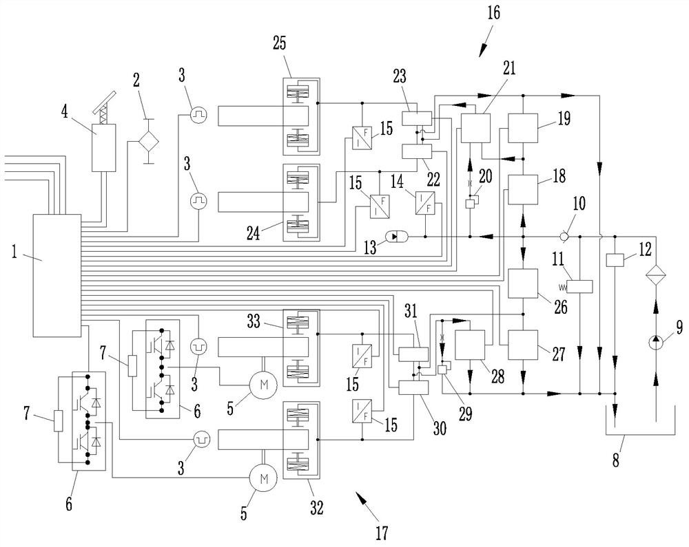
[0028] Such as figure 1 As shown, a control strategy for the braking system of an electric drive dump truck. The dump truck includes two front wheels and two rear wheels. The braking system includes a control module and a braking module. The braking module includes a An electric brake unit for applying braking force individually and a hydraulic brake unit for applying braking force individually to each wheel.

[0029] The control module collects the dump truck information and the driver's control signal and controls the brake module to work. The control module includes a control unit 1, a load sensor 2, a speed sensor 3 corresponding to a single wheel and a brake pedal 4.

[0030] The electric braking unit includes two generators 5 respectively arranged at the two rear wheels, a converter 6 connected to the output ends of the generators 5 and a brakin...


PUM


Abstract

A control strategy for the braking system of an electric drive dump truck. The braking system of the dump truck controls each wheel individually. The braking system includes a control module and a braking module. The control module includes a control unit and a speed sensor corresponding to a single wheel And the brake pedal, the control unit collects the speed signal of the corresponding wheel through the speed sensor, and judges whether the speed of each wheel is synchronous. If the speed is the same, when the control unit detects that any front wheel is locked and slips through the speed sensor, the control unit controls the brake module to reduce the braking force of the locked wheel; the control unit judges whether it is Emergency braking is required, and emergency braking can provide maximum braking force to the dump truck. Adoption of the scheme improves braking reliability and driving safety.

Description

technical field [0001] The invention relates to the technical field of dump truck braking, in particular to a control strategy for an electric drive dump truck braking system. Background technique [0002] Electric drive dump trucks are mainly used in large-scale open-pit mines and earthwork construction sites to transport minerals, earthwork and other materials. The reliability of the braking system is related to the safety of equipment and personal safety on the job site. As users continue to pursue production efficiency, electric drive dump trucks are gradually developing towards larger tonnages. Due to the impact of space, the components of the braking system cannot be the same as the complete vehicle. By increasing the size, they can obtain greater braking force and improve safety. , had to adopt other methods, resulting in a series of problems. In addition, there is still room for optimization in the control strategy of the braking system of the main electric drive du...

Claims


Application Information

Patent Timeline
Patent Type & Authority Patents(China)
IPC IPC(8): B60T8/171B60T8/176B60T8/32B60T13/68
CPCB60T8/171B60T8/32B60T8/176B60T13/686B60T2250/04
Inventor 邹勇陈宣文唐巨铭刘鹏张义亮
Owner GUANGZHOU ELECTRICAL LOCOMOTIVE
Learn More