Position-correctable rail-type dynamic wireless charging system and position correction method

A wireless charging, rail-type technology, applied in the direction of circuit devices, electrical components, etc., can solve the problems of low offset detection accuracy, insufficient detection accuracy, and inaccurate position adjustment, so as to achieve efficient energy transfer and improve anti-offset performance, and the effect of improving the accuracy of position shift detection

Active Publication Date: 2022-08-02
JIANGSU ELECTRIC POWER CO +2
View PDF2 Cites 0 Cited by
  • Summary
  • Abstract
  • Description
  • Claims
  • Application Information

AI Technical Summary

Problems solved by technology

The existing dynamic guidance technology generally uses a single wire or magnetic nail for line tracking, and the deviation detection accuracy is not high. For the dynamic wireless power supply system based on the energy emission guide rail, the deviation information detection cannot be well realized.
In addition, for coordinate positioning methods, such as ultrasonic positioning and GPS positioning, although accurate position calibration can be achieved, the detection accuracy is still not high enough, resulting in inaccurate position adjustment, and the anti-offset of the guide rail dynamic wireless charging system is still relatively large upside

Method used


Image

  • Position-correctable rail-type dynamic wireless charging system and position correction method
  • Position-correctable rail-type dynamic wireless charging system and position correction method
  • Position-correctable rail-type dynamic wireless charging system and position correction method

Examples


Embodiment Construction

[0028] The embodiments of the present invention will be explained in detail below in conjunction with the accompanying drawings. The examples are given only for the purpose of illustration and should not be construed as a limitation of the present invention. The accompanying drawings are only used for reference and description, and do not constitute a limitation on the protection scope of the patent of the present invention. limitation, since many changes may be made in the present invention without departing from the spirit and scope of the invention.

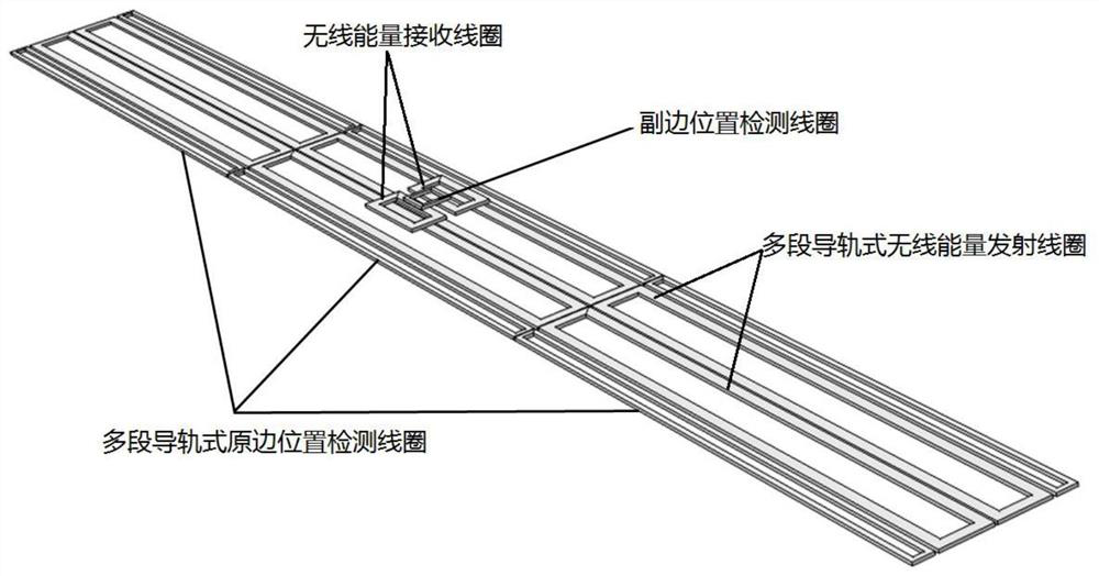
[0029] This embodiment provides a position-correctable rail-type dynamic wireless charging system, including a primary side structure (or called a transmitting end) and a secondary side structure (or called a receiving end). like figure 1 As shown in the three-dimensional structure, the primary side structure includes a horizontally placed multi-segment guide rail type wireless energy transmitting coil (referred to as energy t...


PUM


Abstract

The invention relates to the technical field of rail-type dynamic wireless charging, and specifically discloses a rail-type dynamic wireless charging system that can correct the position and a position correction method thereof. The multi-segment rail-type primary position detection coils on both sides of the rail-type wireless energy transmitting coil, and the secondary side structure includes a wireless energy receiving coil adapted to the multi-segment rail-type wireless energy transmitting coil and a secondary position arranged above the wireless energy receiving coil. detection coil. The present invention reflects the change of the coupling condition of the primary and secondary side position detection coils by detecting the current change of the primary side position detection coil, and then detects the position deviation of the secondary side structure, and further adjusts the position of the secondary side structure, thereby improving the guide rail type. The position offset detection accuracy of the dynamic wireless charging system improves the offset resistance of the rail-type dynamic wireless charging system and realizes the efficient energy transfer of the primary and secondary side structures.

Description

technical field [0001] The invention relates to the technical field of rail-type dynamic wireless charging, in particular to a rail-type dynamic wireless charging system capable of correcting the position and a position correction method thereof. Background technique [0002] In orbital dynamic wireless charging applications, such as AGVs and wireless charging systems for inspection robots, it is an inevitable problem to detect whether the receiving end deviates from the charging orbit and correct it in real time. The existing dynamic guidance technology generally uses a single wire or a magnetic nail for line tracking, and the offset detection accuracy is not high. For the dynamic wireless power supply system based on the energy emission guide rail, the offset information detection cannot be well realized. In addition, for coordinate positioning methods, such as ultrasonic positioning and GPS positioning, although accurate position calibration can be achieved, the detection...

Claims


Application Information

Patent Timeline
Patent Type & Authority Patents(China)
IPC IPC(8): H02J50/90H02J50/12H02J50/00H02J50/40
CPCH02J50/90H02J50/12H02J50/005H02J50/40
Inventor 殷勇许庆强王成亮肖宇华吴涛杨庆胜徐妍王智慧唐春森左志平李小飞贾亚辉张振
Owner JIANGSU ELECTRIC POWER CO
Why Eureka
Try Eureka