Self-checking device and method for water flow control device

A technology of self-checking device and water flow control, applied in the direction of valve device, valve operation/release device, valve details, etc., can solve the problem of loss of closing function, etc., achieve the effect of saving labor, saving water resources, and avoiding damage

Pending Publication Date: 2021-02-23
陈方斌
View PDF0 Cites 0 Cited by
  • Summary
  • Abstract
  • Description
  • Claims
  • Application Information

AI Technical Summary

Problems solved by technology

[0009] Aiming at the problem that there is no method in the prior art to realize the self-inspection of the important component "fluid electric control valve", the purpose of the present invention is to provide a self-inspection device and method for a water flow control device, which can solve or avoid the problems in the background art. Problems, through the self-inspection procedure within the cycle in time, you can know whether the fluid electric control valve is damaged or whether it has lost the closing function, which is beneficial for people to repair or replace it in time, and avoid property loss and waste caused by the failure of the water control device

Method used


Image

  • Self-checking device and method for water flow control device
  • Self-checking device and method for water flow control device
  • Self-checking device and method for water flow control device

Examples


Embodiment 1

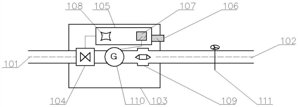
[0048] like figure 1 As shown, the self-inspection device of a water flow control device provided in this embodiment is a self-inspection device of a water flow control device, which includes water pipes 101 and 102 through which the water flows. A fluid electric control valve 104, an intelligent control module 105, a water flow sensor 109, and a water intake valve 111 are provided. The water intake valve 111 is a terminal for users to obtain water, and the intelligent control module 105 is provided with a power supply 107 for providing energy;

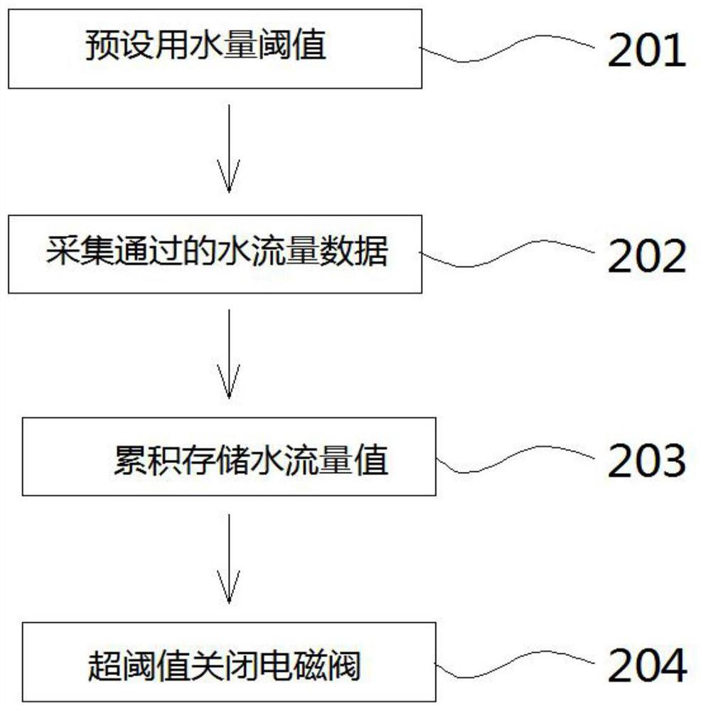
[0049] The intelligent control module 105 is used to power off the fluid electric control valve 104 and close the water flow when it is judged that the accumulated water flow value of the water flow sensor 109 exceeds a preset threshold;

[0050] The power supply 107 is connected to the fluid electric control valve 104, the intelligent control module 105, and the water flow sensor 109 respectively, and is used to provide power for the...

Embodiment 2

[0053] like figure 1 and figure 2 As shown, similar to Embodiment 1, in this embodiment, the chip 108 pre-stores data, is located on the intelligent control module 105, and controls the fluid electronic control valve 104 through the intelligent control module 105;

[0054] The water intake valve 111 is a quick-open valve, including a faucet that can reach the maximum flow of water when the angle is not more than 90°;

[0055] The water pipe passes through the box body 103 through the through holes on both sides of the box body 103, and the water flow in the water pipe flows from the water pipe inlet 101 on the outer side of the box body 103 to the water pipe outlet 102 on the other side of the box body 103;

[0056] The right side of the intelligent control module 105 is provided with a manual reset key 106, which is used to manually restore the normal reset of the entire water control device including the fluid electric control valve 104; The through hole is installed on t...

Embodiment 3

[0058] like figure 1 and figure 2 As shown, similar to Embodiment 1, in this embodiment, the power source 107 provided in the intelligent control module 105 is an energy storage power source, including a battery pack. The present embodiment is also provided with a generator 110 installed in the casing 103, and the generator 110 is connected to the power supply 107;

[0059] The generator 110 relies on the kinetic energy of flowing water flowing from the water pipe inlet 101 to the water pipe outlet 102 to generate electricity by itself, and the generated electric energy is stored in the power source 107 .


PUM


Abstract

The invention discloses a self-checking device and method for a water flow control device, and belongs to the technical field of switch control. The self-checking device comprises a water pipe, wherein a self-checking device body is in a box shape, a fluid electric control valve, an intelligent control module and a water flow sensor are arranged in the box, a water taking valve outside the box isa terminal for a user to take water, and a power supply for providing energy is arranged in the intelligent control module; the intelligent control module is used for enabling the fluid electric control valve to be powered off to close water flow when that the water flow value accumulated by the water flow sensor exceeds a preset threshold value is judged; and the power supply is connected with the fluid electric control valve, the intelligent control module and the water flow sensor and used for providing electric energy. The self-checking device further comprises a chip, the chip sets a periodic self-checking program and periodically and automatically resets, and whether a whole water protection device can be normally used or not is detected by detecting whether the fluid electric control valve normally works or not. The self-checking device has the automatic water control function and the self-checking function on the fluid electric control valve.

Description

technical field [0001] The invention relates to the field of switch control, in particular to a self-checking device of a water flow control device and a method for using the same. Background technique [0002] Water, without a doubt, is very important to most living individuals! Water is an important resource on the earth where we live, and it is of great significance to human beings. In general, the water consumption of water installations is predictable. Generally, household water is about 1000-6000 liters a day. If the water device fails to close the valve or faucet, the water will continue to flow out, which will not only cause waste of water resources, but what is even worse is that the indoor water will damage the home floor and damage the furniture. Appliances, causing more serious property damage. Some floor dwellings even leak water for a long time due to broken water pipes and other reasons, and it has not been discovered that it has caused disasters to other p...

Claims


Application Information

Patent Timeline
Patent Type & Authority Applications(China)
IPC IPC(8): F16K37/00F16K31/06
CPCF16K31/06F16K37/005
Inventor 陈方斌
Owner 陈方斌
Why Eureka
Try Eureka