Telescopic barrier gate

A telescopic, barrier technology, applied in the directions of roads, roads, road signs, etc., can solve the problems of barrier and vehicle damage, slow opening and closing speed, and high energy consumption, so as to avoid accelerated card punching, improve The effect of utilization and fast response speed

Active Publication Date: 2021-02-23
深圳市财门智能科技有限公司
View PDF7 Cites 0 Cited by
  • Summary
  • Abstract
  • Description
  • Claims
  • Application Information

AI Technical Summary

Problems solved by technology

[0002] Barrier gates will be set up at the intersections where trains pass and the roads in front of some schools to restrict the passage of vehicles. The more common barrier gates are usually swing arm barrier gates and mobile barrier gates. The length of the arm is not suitable for wider road use, and the mobile barrier gate, which opens and closes slowly, is not suitable for wider road use
[0003] In order to ensure the smoothness of the road and realize the opening and closing of wider roads at the fastest speed, a hydraulic lifting barrier has appeared on the market. The hydraulic cylinder is embedded in the ground, and when the road is closed, the hydraulic column is driven to extend out. , to close the road, but because there is a visual blind spot directly in front of the vehicle, when the vehicle stops too close to the switch, it is impossible to see whether the barrier is fully retracted. Start the vehicle while retracting and hit the barrier, causing damage to both the barrier and the vehicle
[0004] Secondly, the hydraulic lift type barrier gate needs to provide power when it is raised and retracted, and compared with the swing arm type and mobile barrier gate, the energy consumption will be larger, and there is a demand for energy saving. Moreover, in daily use, some drivers have an adventurous heart and want to accelerate and rush past the barrier gate when it is about to rise or is not fully raised. At this time, the impact fails and a larger accident will occur.

Method used


Image

  • Telescopic barrier gate
  • Telescopic barrier gate
  • Telescopic barrier gate

Examples


Embodiment Construction

[0019] The following will clearly and completely describe the technical solutions in the embodiments of the present invention with reference to the accompanying drawings in the embodiments of the present invention. Obviously, the described embodiments are only some of the embodiments of the present invention, not all of them. Based on the embodiments of the present invention, all other embodiments obtained by persons of ordinary skill in the art without making creative efforts belong to the protection scope of the present invention.

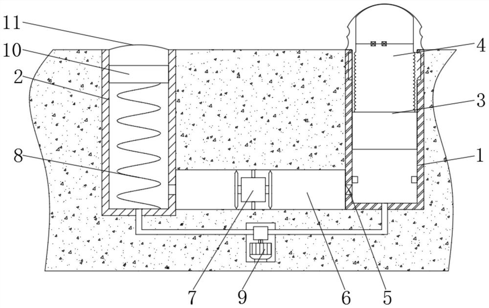
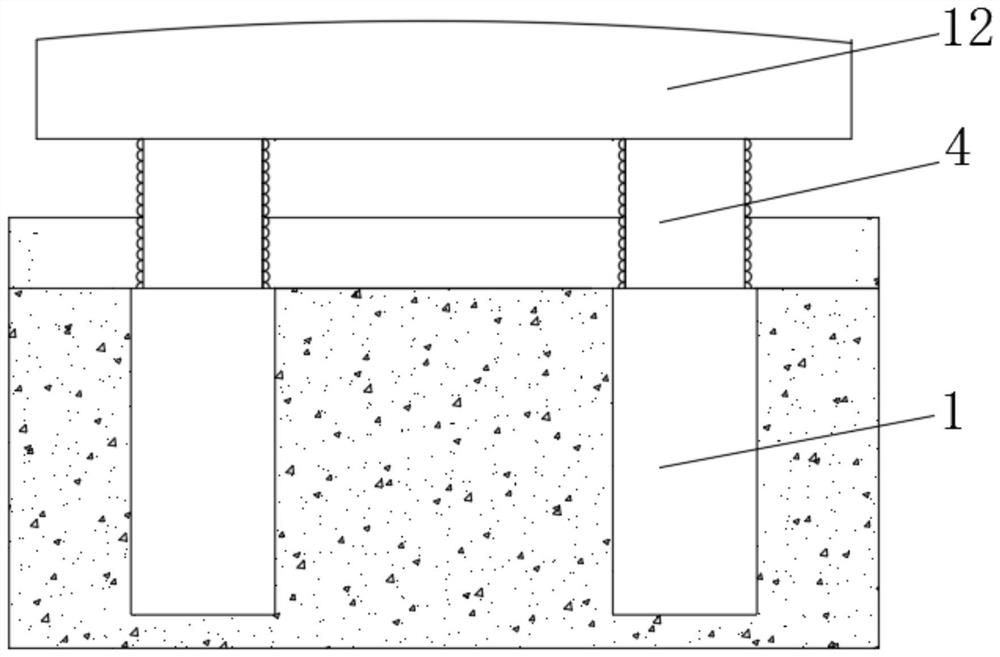
[0020] see figure 1 , a telescopic barrier, including a driving cylinder 1 and an energy storage cylinder 2 embedded in the intersection, the energy storage cylinder 2 is located in the direction of the vehicle coming from the driving cylinder 1, the driving cylinder 1 and the energy storage cylinder 2 are both pneumatic cylinders, and the driving cylinder 1 is equipped with a plunger 3, and the upper end of the plunger 3 is provided with a flexi...


PUM


Abstract

The invention relates to the technical field of municipal equipment, and discloses a telescopic barrier gate which comprises a driving cylinder and an energy storage cylinder which are embedded into an intersection, the driving cylinder and the energy storage cylinder are both pneumatic cylinders, and a plunger is assembled in the driving cylinder. Due to the fact that the extending part is composed of the identification column capable of being compressed and deformed and the plunger, when the whole body retracts into the road surface and the top of the identification column is small and is located in the visual blind area of the automobile, the plunger is lower than the chassis, the identification column is compressed and deformed only when the automobile passes, and on the other hand, the pillow bag is higher than the road surface and expansion plastic fluid in the pillow bag can play a speed-limiting role, driver accelerated barrier gate punching during rising countdown is effectively avoided. Secondly, compared with a hydraulic cylinder, the pneumatic cylinder is higher in response speed, the plunger and the identification column can be driven to retract in extreme time, the probability that the identification column and the plunger do not retract in time and collide with a vehicle is further reduced, and when the vehicle passes by and the barrier gate retracts, residual kinetic energy or potential energy can be used for power generation.

Description

technical field [0001] The invention relates to the technical field of municipal equipment, in particular to a telescopic barrier gate. Background technique [0002] Barrier gates will be set up at the intersections where trains pass and the roads in front of some schools to restrict the passage of vehicles. The more common barrier gates are usually swing arm barrier gates and mobile barrier gates. The length of the arm is not suitable for use on wider roads, and the speed of opening and closing of mobile barrier gates is slow, so it is not suitable for use on wider roads. [0003] In order to ensure the smoothness of the road and realize the opening and closing of wider roads at the fastest speed, a hydraulic lifting barrier has appeared on the market. The hydraulic cylinder is embedded in the ground, and when the road is closed, the hydraulic column is driven to extend out. , to close the road, but because there is a visual blind spot directly in front of the vehicle, whe...

Claims


Application Information

Patent Timeline
Patent Type & Authority Applications(China)
IPC IPC(8): E01F13/04E01F9/608F01D15/10
CPCE01F13/046E01F9/608F01D15/10Y02E70/30
Inventor 赵娟
Owner 深圳市财门智能科技有限公司
Why Eureka
Try Eureka