
Pressure device that can be parked at will

A pressure device, arbitrary parking technology, applied in the direction of fluid pressure actuation device, servo motor assembly, mechanical equipment, etc., can solve the problems of restricted product market promotion, piston stuck, and high cost

Active Publication Date: 2015-12-23
杨关金
View PDF5 Cites 0 Cited by
  • Summary
  • Abstract
  • Description
  • Claims
  • Application Information

AI Technical Summary

Problems solved by technology

[0003] For the method of using a special control switch to control the parking, once the control switch fails, the piston in the pressure elastic element will be stuck, which can neither continue to stretch nor compress
In the specific production, due to the need to use manual handles, electronic switches and other equipment for control outside the pressure elastic element, the cost of producing such products is also high, thus limiting the market promotion of related products

Method used


Image

  • Pressure device that can be parked at will
  • Pressure device that can be parked at will
  • Pressure device that can be parked at will

Examples


Embodiment Construction

[0018] The present invention will be further described below in conjunction with the accompanying drawings.

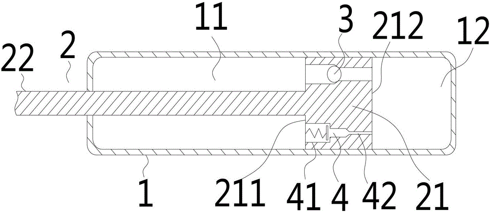
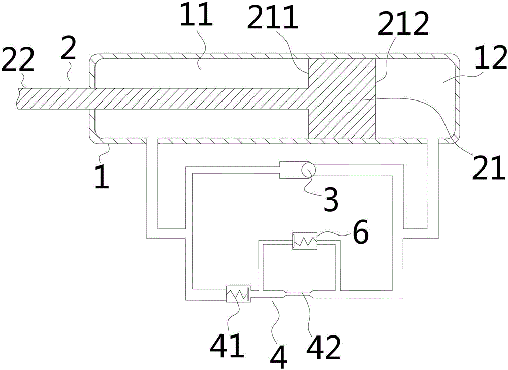
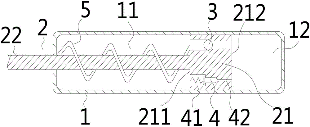
[0019] Such as figure 1 , figure 2 , image 3 , Figure 4 The shown pressure device that can be parked arbitrarily includes a pressure tube 1 and a piston 2 sleeved in the pressure tube 1. The piston head 21 of the piston 2 divides the inner cavity of the pressure tube 1 into a medium cavity 11 and a pressure cavity. 12. It is characterized in that it includes a one-way valve 3 and an overrun self-closing valve 41. The two ends of the overrun self-closing valve 41 communicate with the medium chamber 11 and the pressure chamber 12 respectively, and the flow direction of the overrun self-closing valve 41 is medium The chamber 11 flows to the pressure chamber 12, the two ends of the one-way valve 3 communicate with the medium chamber 11 and the pressure chamber 12 respectively, and the flow direction of the one-way valve 3 is that the pressure chamber 12 flows to the ...


PUM


Abstract

The invention relates to the field of elastic pressure devices, in particular to a pressure device capable of stopping at any position. The pressure device can stop at any position. According to the technical scheme, the pressure device capable of stopping at any position comprises a pressure pipe and a piston sleeved with the pressure pipe, and the inner cavity of the pressure pipe is divided into a medium cavity and a pressure cavity through the piston head of the piston. The pressure device capable of stopping at any position further comprises a one-way valve and a stopping control valve which is formed by connecting an over-limit self-closing valve and a flow control valve in series, the over-limit self-closing valve of the stopping control valve is communicated with the medium cavity, the flowing direction of the over-limit self-closing valve is the direction in which media flow from the medium cavity to the pressure cavity, the flow control valve of the stopping control valve is communicated with the pressure cavity, and therefore the piston can stop at any position repeatedly. The pressure device capable of stopping at any position can be applied on occasions when the pressure device needs to stop at any position in mechanical equipment, electronic equipment and the like.

Description

technical field [0001] The invention relates to the field of elastic pressure devices, in particular to a pressure device that can be parked arbitrarily. Background technique [0002] In products such as pressure elastic support rod elements, dampers, etc., in order to allow the pressure elastic element to stop during the movement stroke and keep it at a fixed position, the current technology is to set a special control switch to control the working medium. The special control switches include manual handles, electronic switches and other equipment. [0003] For the method that the special control switch adopted is used to control the parking, once the control switch breaks down, the piston in the pressure elastic element will be blocked, and cannot continue to stretch or compress. In the specific production, since it is necessary to use devices such as manual handles and electronic switches for control in addition to the pressure elastic element, the cost of producing such...

Claims


Application Information

Patent Timeline
Patent Type & Authority Patents(China)
IPC IPC(8): F15B13/02
Inventor 杨关金
Owner 杨关金
Learn More