diaphragm tank
A diaphragm and storage tank technology, which is used in space navigation equipment, space navigation equipment, transportation and packaging, etc., can solve the problem of no resistance to liquid shaking, and achieve the effects of improved space utilization, good safety and high reliability.
- Summary
- Abstract
- Description
- Claims
- Application Information
AI Technical Summary
Problems solved by technology
Method used
Image
Examples
Embodiment 1
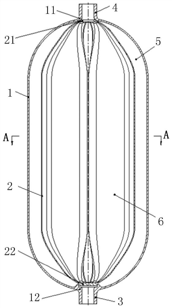
[0040] The present invention provides a diaphragm tank, comprising a tank shell 1 and a gas-liquid diaphragm 2, the shape and structure of the tank shell 1 includes various forms, preferably such as figure 1 The shown combination is a cylindrical structure in the middle and a tangential spherical or hemispherical structure at both ends. In addition, according to the actual application scenario, a structure such as a shuttle structure or a spindle-like structure, or other suitable structures can also be used. The structural form to meet the needs of practical applications.
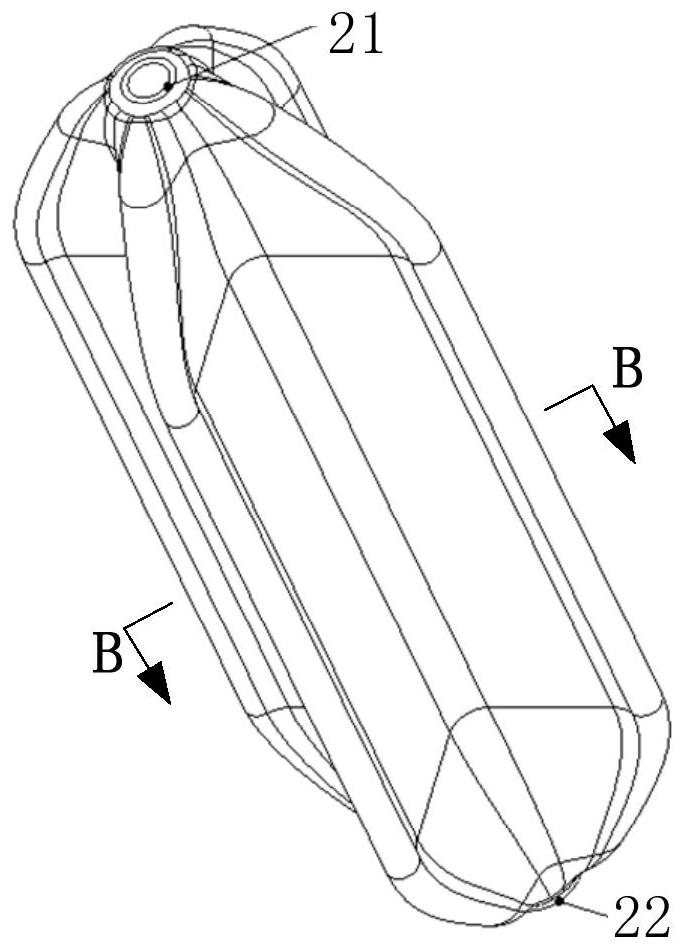
[0041] Specifically, the two ends of the storage tank shell 1 are respectively provided with a filling and discharging port 11 and a liquid filling and discharging port 12 at the poles of the head of the two ends, and the two ends of the gas-liquid diaphragm 2 are respectively an open end 21 and a blind hole end. 22. The gas-liquid diaphragm 2 is arranged inside the tank shell 1 and a liquid storage cavity ...
Embodiment 2
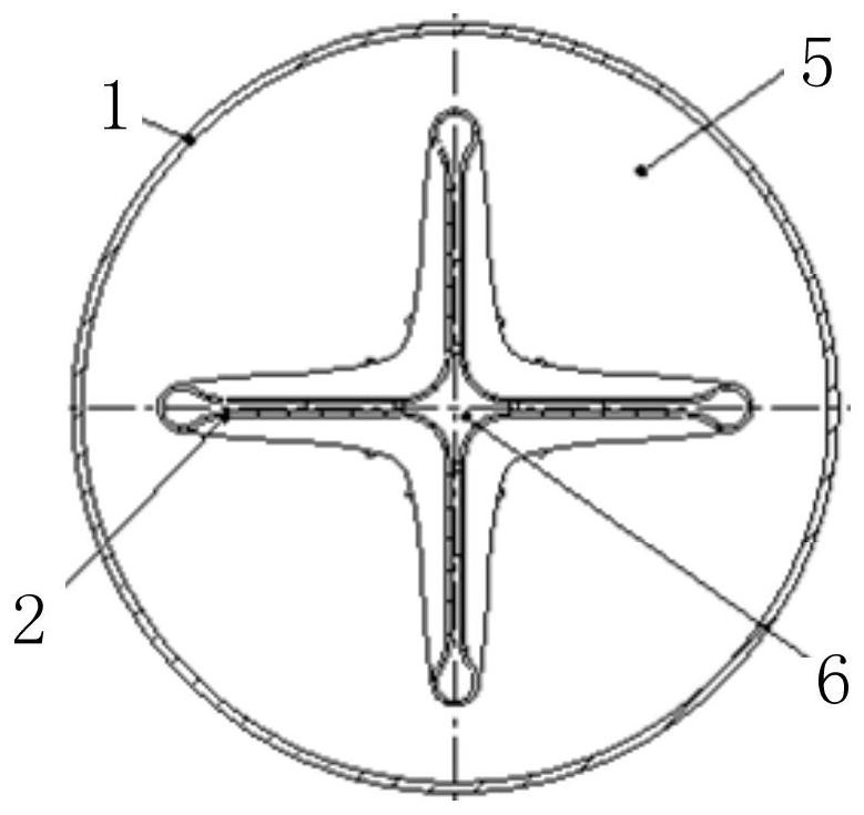
[0049] Such as figure 1 As shown, a diaphragm storage tank includes a storage tank shell 1, and the two ends of the storage tank shell 1 are respectively provided with an inflation and discharge port 11 and a liquid addition and discharge port 12, and the gas-liquid diaphragm 2 is arranged on the storage tank. At the axis of the inner cavity of the tank shell 1, the opening end 21 of the gas-liquid diaphragm 2 is in sealing connection with the filling and deflation port 11 of the tank shell 1, and the blind hole end 22 is connected with the charging port 11 of the tank shell 1. The liquid port 12 is connected, and the outer wall surface of the gas-liquid diaphragm 2 forms a liquid storage chamber 5 with the inner wall surface of the tank shell 1, and the inner wall surface of the gas-liquid diaphragm 2 forms a gas storage chamber 6, which can be combined with The inner wall surface of the storage tank shell 1 is bonded; the liquid connection nozzle 3 is in sealing connection w...
Embodiment 3
[0057] This embodiment is an improved manner based on the second embodiment.
[0058] Specifically, in this embodiment, the cross-section of the gas-liquid diaphragm 2 is a hollow "*"-shaped structure, made of non-metallic materials, and the wall thickness is 0.2mm-2.0mm.
[0059] Specifically, in this embodiment, the opening end 21 of the gas-liquid diaphragm 2 is connected to the gas filling and deflation port 11 of the tank shell 1 with a flange seal.
[0060] Specifically, in this embodiment, the blind hole end 22 of the gas-liquid diaphragm 2 and the liquid filling and discharging port 12 of the tank shell 1 are connected by a flange seal, and at the same time, the blind hole end 22 is fixed and role of positioning.
PUM
 Abstract
Description
Claims
Application Information
 - R&D
- Intellectual Property
- Life Sciences
- Materials
- Tech Scout
- Unparalleled Data Quality
- Higher Quality Content
- 60% Fewer Hallucinations
Browse by: Latest US Patents, China's latest patents, Technical Efficacy Thesaurus, Application Domain, Technology Topic, Popular Technical Reports.
© 2025 PatSnap. All rights reserved.Legal|Privacy policy|Modern Slavery Act Transparency Statement|Sitemap|About US| Contact US: help@patsnap.com


