Oil-immersed power transformer
An oil-immersed technology for power transformers, applied in the field of transformers, can solve the problems of low heat dissipation efficiency and incapable heat dissipation of transformer oil, and achieve the effects of improving heat dissipation efficiency, reducing oil heat, and avoiding influence
- Summary
- Abstract
- Description
- Claims
- Application Information
AI Technical Summary
Problems solved by technology
Method used
Image
Examples
Embodiment 1
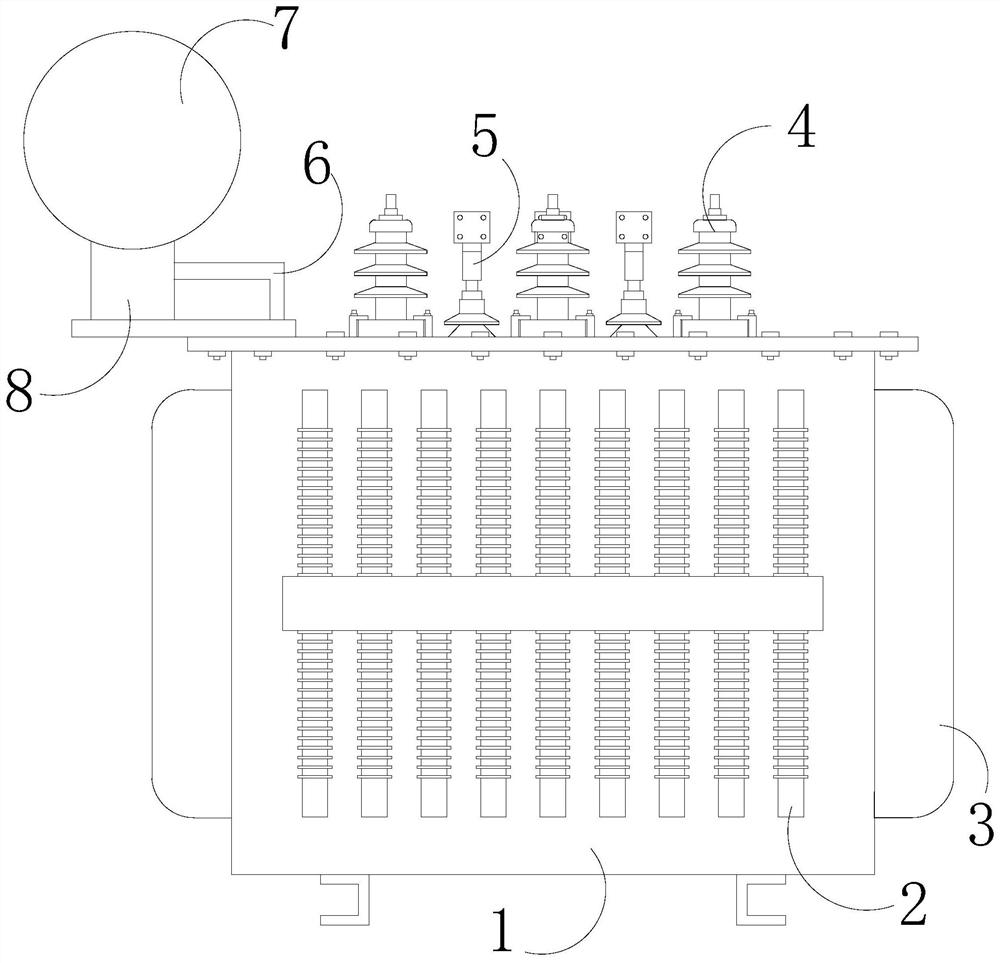
[0031] see Figure 1-5 , the present invention provides a technical solution for an oil-immersed power transformer: an oil-immersed power transformer, the structure of which includes an oil tank 1, a heat dissipation device 2, a corrugated heat sink 3, a high-voltage terminal 4, a low-voltage terminal 5, an oil pipe 6, Oil conservator 7, support frame 8, the top of described oil tank 1 is mechanically connected with support frame 8, and oil conservator 7 is installed on described support frame 8, and described oil conservator 7 communicates with fuel tank 1 through oil pipe 6, and described fuel tank 1 A high-voltage terminal 4 and a low-voltage terminal 5 are installed on the top surface of the fuel tank 1 , corrugated heat sinks 3 are provided on both sides of the fuel tank 1 , and a heat sink 2 is installed on the front of the fuel tank 1 .
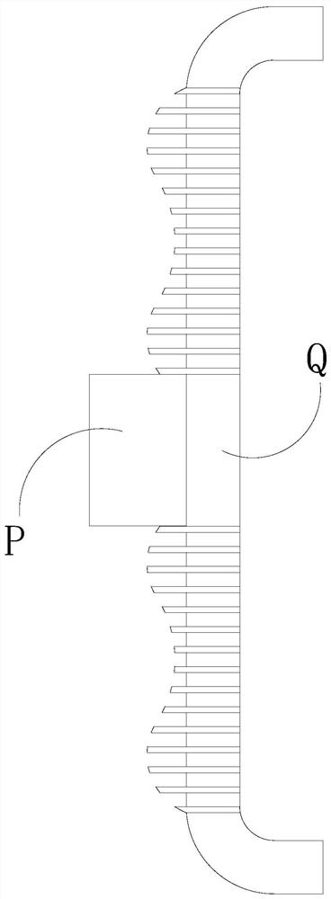
[0032] The heat dissipation device 2 includes a heat dissipation pipe Q and a power connection box P. There are nine heat dissipation...
Embodiment 2
[0040] see Figure 1-3 , 6-9, the present invention provides a technical solution for an oil-immersed power transformer: an oil-immersed power transformer, the structure of which includes an oil tank 1, a heat sink 2, a corrugated heat sink 3, a high-voltage terminal 4, and a low-voltage terminal 5 , oil pipe 6, oil conservator 7, support frame 8, the top of described fuel tank 1 is mechanically connected with support frame 8, and described support frame 8 is equipped with oil conservator 7, and described oil conservator 7 communicates with fuel tank 1 through oil pipe 6, A high-voltage terminal 4 and a low-voltage terminal 5 are installed on the top surface of the fuel tank 1 , corrugated heat sinks 3 are provided on both sides of the fuel tank 1 , and a heat sink 2 is installed on the front of the fuel tank 1 .
[0041] The heat dissipation device 2 includes a heat dissipation pipe Q and a power connection box P. There are nine heat dissipation pipes Q, and the nine heat dis...
PUM
 Abstract
Description
Claims
Application Information
 - R&D
- Intellectual Property
- Life Sciences
- Materials
- Tech Scout
- Unparalleled Data Quality
- Higher Quality Content
- 60% Fewer Hallucinations
Browse by: Latest US Patents, China's latest patents, Technical Efficacy Thesaurus, Application Domain, Technology Topic, Popular Technical Reports.
© 2025 PatSnap. All rights reserved.Legal|Privacy policy|Modern Slavery Act Transparency Statement|Sitemap|About US| Contact US: help@patsnap.com


