Optical cable terminal box based on data supervision and early warning

A technology of data supervision and terminal box, used in optics, light guides, optical components, etc.

Pending Publication Date: 2021-02-19
杭州奥克光电设备有限公司
View PDF8 Cites 1 Cited by
  • Summary
  • Abstract
  • Description
  • Claims
  • Application Information

AI Technical Summary

Problems solved by technology

[0004] The purpose of the present invention is to provide an optical cable terminal box based on data supervision and early warning, which solves the following technical problems: (1) By opening a screw hole on the wall corresponding to the position of the screw, the bottom of the terminal box cover is placed on the wall, Turn on the lifting motor, the output shaft of the lifting motor drives the pulley to rotate, several pulleys rotate in the same direction, the pulleys coaxially drive the screw to rotate, turn on the lifting cylinder, the piston rod of the lifting cylinder pushes the lifting plate, the lifting plate drives the screw to move out of the cover base, and the screw rotates Insert it into the screw hole on the wall to complete the fixing of the terminal box cover. Through the above structural settings, the optical cable terminal box is convenient to install on the wall. Just open the screw hole on the wall, and the screw can be automatically rotated and inserted (2) The water in the terminal box cover is absorbed by the absorbent cotton in the first serpentine tube, the condensate pump pumps the water in the first serpentine tube, and the condensate pump delivers the condensed water to the second serpentine tube , the condensed water in the second serpentine tube flows back into the first serpentine tube to form a condensed water cycle, the drive motor is turned on, the output shaft of the drive motor drives gear three to rotate, gear three drives gear four to rotate, and gear four drives the second serpentine tube to rotate , the rotation of the second serpentine tube generates cold air to dissipate heat in the inner cavity of the terminal box cover, the adjustment motor is turned on, the output shaft of the adjustment motor drives the first lead screw to rotate, the first lead screw drives the two adjustment sleeves to move toward each other, and the two adjustment sleeves drive The two side baffles move towards each other, the side baffle cancels the blocking of the heat dissipation fins, the heat in the terminal box cover is discharged to the outside through the heat dissipation fins, and the design of the absorbent cotton in the first serpentine tube effectively prevents the cable terminal box from Too much moisture in the cavity will cause the electrical components to be damp. At the same time, when the internal temperature of the optical cable terminal box is too high, the absorbed moisture will be condensed, and the cold wind formed by the rotation of the second serpentine tube will dissipate the heat in the inner cavity of the optical cable terminal box. Through the design of the adjustable side baffle, the side baffle blocks the heat dissipation fins when no heat dissipation is required, preventing external dust from entering the inner cavity of the optical cable terminal box through the heat dissipation fins; (3) When the buffer plate is hit, the buffer The plate drives the guide block to slide on the guide rod through the buffer rod, and the guide block drives the buffer spring to expand and contract, which buffers the impact of the buffer plate. Through the above structure, the front of the optical cable terminal box is effectively buffered when it is impacted, and will not be directly Damage to the display and warning lights

Method used


Image

  • Optical cable terminal box based on data supervision and early warning
  • Optical cable terminal box based on data supervision and early warning
  • Optical cable terminal box based on data supervision and early warning

Examples


Embodiment Construction

[0031] The following will clearly and completely describe the technical solutions in the embodiments of the present invention with reference to the accompanying drawings in the embodiments of the present invention. Obviously, the described embodiments are only some, not all, embodiments of the present invention. Based on the embodiments of the present invention, all other embodiments obtained by persons of ordinary skill in the art without creative efforts fall within the protection scope of the present invention.

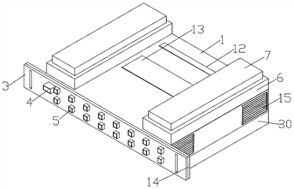
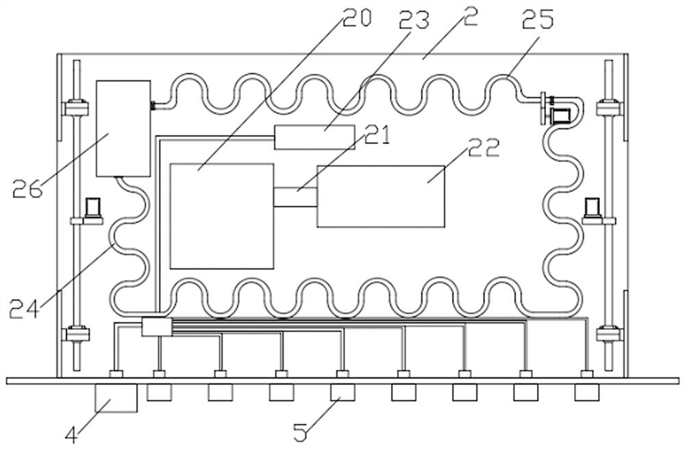
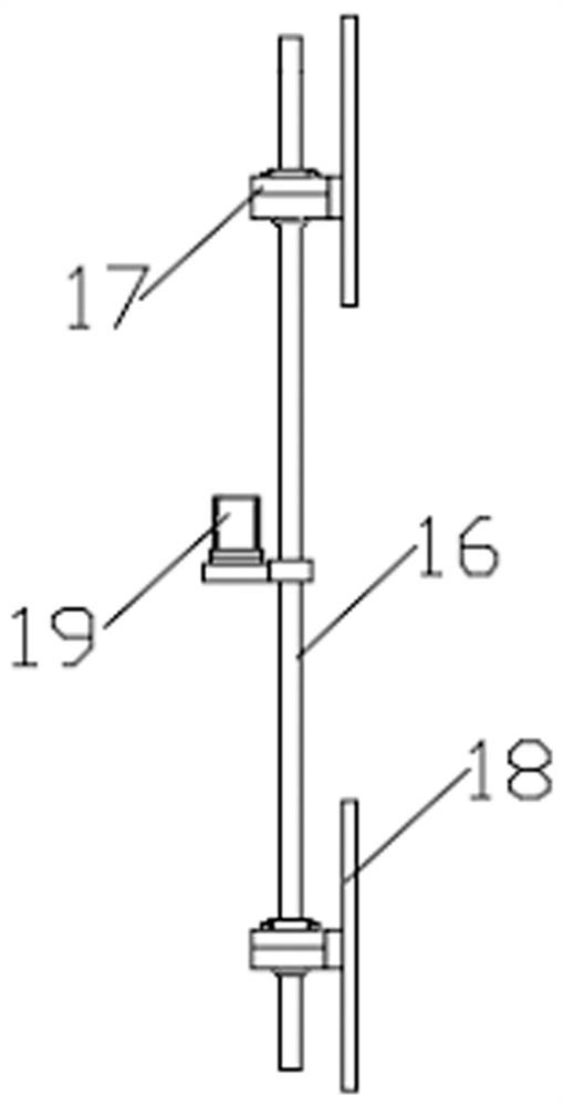
[0032] see Figure 1-7 As shown, the present invention is an optical cable terminal box based on data supervision and early warning, which includes a terminal box cover 1, a drawer plate 2, the drawer plate 2 is slidably connected to the terminal box cover 1, and one side of the drawer plate 2 is installed with Dust-proof baffle 3, the main optical fiber ferrule 4 is installed on the dust-proof baffle 3, several shunt fiber optic ferrules 5 are installed on the dus...


PUM


Abstract

The invention discloses an optical cable terminal box based on data supervision and early warning. The optical cable terminal box comprises a terminal box cover and a drawing supporting plate, whereinthe drawing supporting plate is slidably connected with the terminal box cover, a dustproof baffle is installed on one side of the drawing supporting plate, a main optical fiber sleeve head is installed on the dustproof baffle, a plurality of shunt optical fiber sleeve heads are installed on the dustproof baffle, and two buffer bases are installed on the terminal box cover. According to the invention, the optical cable terminal box is convenient to install on a wall surface; a screw rod can be automatically rotated and inserted into a screw hole only by forming the screw hole in the wall surface; the situation that an electric device is affected with damp due to excessive moisture in the inner cavity of the optical cable terminal box is effectively prevented through the design of absorbent cotton in a first coiled pipe, and meanwhile, absorbed moisture is condensed when the inner temperature of the optical cable terminal box is too high; the inner cavity of the optical cable terminalbox is cooled through cold air formed by rotation of a second coiled pipe; and through the design of an adjustable side baffle plate, the side baffle plate blocks heat dissipation fins when heat dissipation is not needed, so external dust is prevented from entering the inner cavity of the optical cable terminal box through the heat dissipation fins.

Description

technical field [0001] The invention relates to the technical field of optical cable terminal box design, in particular to an optical cable terminal box based on data supervision and early warning. Background technique [0002] In the field of broadband access, most households in China use ADSL technology to implement it, and various services of users enter the core network through the access network. With the continuous and rapid development of the Internet, new online services emerge in an endless stream, especially the interactive games, video calls and IPTV that have become popular in recent years, making people's demand for network access bandwidth continue to increase, because ordinary ADSL technology cannot provide long-distance A series of services such as high-speed broadband and high-speed broadband have gradually been unable to adapt to the launch of more new service items by fixed network operators on the basis of the original bandwidth to meet user needs. There...

Claims


Application Information

Patent Timeline
Patent Type & Authority Applications(China)
IPC IPC(8): G02B6/44F16F15/067
CPCG02B6/4446F16F15/067
Inventor 金辉
Owner 杭州奥克光电设备有限公司
Why Eureka
Try Eureka