Liquid sealed vacuum glass for glass curtain wall

A technology of vacuum glass and glass curtain wall, which is applied to the sealing of vacuum gauges, walls, and engines, etc., which can solve the problems of potential safety hazards, high maintenance costs, and poor practicability, and achieve the elimination of potential safety hazards, high accuracy, and strong practicability Effect

Active Publication Date: 2021-02-19
福建省建筑轻纺设计院有限公司
View PDF4 Cites 0 Cited by
  • Summary
  • Abstract
  • Description
  • Claims
  • Application Information

AI Technical Summary

Problems solved by technology

[0004] The purpose of the present invention is to solve the disadvantages of high maintenance cost, poor practicability, difficult maintenance and potential safety hazards of existing vacuum glass in the prior art, and proposes a liquid-sealed vacuum glass for glass curtain wall

Method used


Image

  • Liquid sealed vacuum glass for glass curtain wall
  • Liquid sealed vacuum glass for glass curtain wall
  • Liquid sealed vacuum glass for glass curtain wall

Examples


Embodiment 1

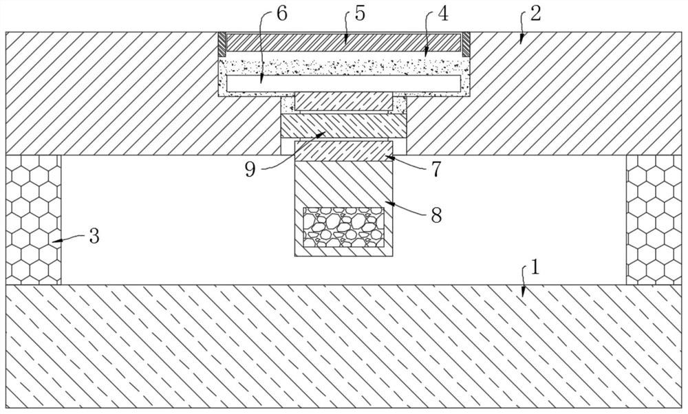
[0021] refer to figure 1 , a liquid-sealed vacuum glass for a glass curtain wall, comprising an outer layer plate 1 and an inner layer plate 2, an annular sealing strip 3 is fixedly arranged between the outer layer plate 1 and the inner layer plate 2, the outer layer plate 1, the inner layer plate 2 The sealed space formed by the layer plate 2 and the sealing strip 3 is a vacuum layer, and the side of the inner layer plate 2 far away from the vacuum layer is provided with a liquid storage tank 4, and the bottom groove wall of the liquid storage tank 4 is connected with the vacuum layer and has a through hole. The liquid tank 4 is slidingly connected with the limit block 6, the lower end of the limit block 6 is coaxial and vertically fixedly connected with the connecting rod 7, and the lower end of the connecting rod 7 extends through the through hole into the vacuum layer and is fixedly connected with the placement box 8, which is located at An annular groove is provided on th...

Embodiment 2

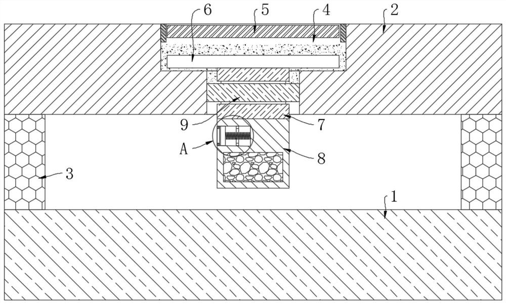
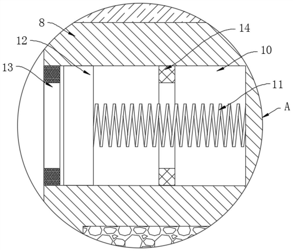
[0026] refer to Figure 2-3 The difference between this embodiment and Embodiment 1 is that: the side wall of the storage box 8 is provided with an installation groove 10, the notch of the installation groove 10 is fixedly provided with a limit ring 13, and the installation groove 10 is vertically fixedly connected with a ring-shaped pressure ring. Electric sheet 14, the groove wall of mounting groove 10 is elastically connected with piston block 12 by limit spring 11, and piston block 12 is connected with the groove wall of mounting groove 10 sealing sliding, and piston block 12 is positioned at piezoelectric sheet 14 and position-limiting Between the rings 13, the piezoelectric sheet 14 is electrically connected with external signal transmitting equipment through wires.

[0027] When the initial vacuum layer is in a vacuum environment, the piston block 12 is subjected to the negative pressure of the vacuum layer to stretch the limit spring 11 and resist the limit ring 13. Wh...


PUM


Abstract

The invention discloses a liquid sealed vacuum glass for a glass curtain wall. The liquid sealed vacuum glass comprises an outer layer plate and an inner layer plate, an annular sealing strip is arranged between the outer layer plate and the inner layer plate in a sealed mode, a sealed space formed by the outer layer plate, the inner layer plate and the sealing strip is a vacuum layer, a liquid storage groove is formed in the side, away from the vacuum layer, of the inner layer plate, the bottom groove wall of the liquid storage groove communicates with the vacuum layer and is provided with athrough hole, and a limiting block is slidably connected into the liquid storage groove. By arranging a permanent magnet disc, magnetorheological fluid, a connecting rod and a sealing ring, a limitingblock, the connecting rod and the sealing ring can form an integral liquid seal by utilizing the form transformation of the magnetorheological fluid in a zero magnetic field environment and a strongmagnetic field environment, the magnetorheological fluid does not flow again when the magnetorheological fluid performs liquid seal on the through hole, so that it is convenient to carry the vacuum glass; and meanwhile, after the permanent magnet disc is separated from the liquid storage groove, the sealing of the through hole can be quickly released, the vacuum glass does not need to be integrally detached, maintenance is convenient, and practicability is high.

Description

technical field [0001] The invention relates to the technical field of glass curtain walls, in particular to a liquid-sealed vacuum glass for glass curtain walls. Background technique [0002] Glass curtain wall structure is a new type of architectural design that uses glass walls instead of traditional bricks. Vacuum glass is a new type of glass product with vacuum interlayer developed based on the principle of vacuum flasks. It has good sound insulation and heat insulation functions. Therefore In order to ensure the sound insulation and heat insulation performance of the glass curtain wall, many glass curtain walls use vacuum glass as the main material of the wall facade. [0003] However, due to the large surface area and small volume of the inner cavity of the existing vacuum glass, the gas infiltrated from the outside causes the gas pressure in the inner cavity to increase at a high rate, the vacuum fails quickly, and the service life is short. In order to ensure the a...

Claims


Application Information

Patent Timeline
Patent Type & Authority Applications(China)
IPC IPC(8): F16J15/14E04B2/88G01L21/00
CPCF16J15/14E04B2/88G01L21/00Y02A30/249Y02B80/22
Inventor 成宏亮
Owner 福建省建筑轻纺设计院有限公司
Why Eureka
Try Eureka