Nondestructive numerical control hydraulic machine for powder strip

A technology of long strips and hydraulic presses, applied in punching machines, presses, manufacturing tools, etc., can solve problems such as product quality decline, occupation of workshop space, inconvenience in large-scale production, etc., and achieve the effect of accurate measurement and extended service life

Pending Publication Date: 2021-02-19
黄静
View PDF0 Cites 1 Cited by
  • Summary
  • Abstract
  • Description
  • Claims
  • Application Information

AI Technical Summary

Problems solved by technology

However, when using a hydraulic press to manufacture long three-dimensional space structural parts for powder compaction, firstly, when using the gravimetric method to measure the weight of metallurgical powder, it is necessary to use weighing scales and related storage and delivery devices to complete the process, which not only takes up the space of the workshop, but also And it is not convenient for large-scale production; the second is that when the feeding port of the feeding hopper is moved from the feeding position to the pressure forming position, there will be fine metallurgical powder remaining between the feeding port and the plane of the working plate. , There are more and more residual metallurgical powder particles, and the hard metallurgical powder particles are bonded together to form larger particles, which will scratch and strain the plane of the mold and the working plate, not only damage the forming mold, but even cause product quality to decline

Method used


Image

  • Nondestructive numerical control hydraulic machine for powder strip
  • Nondestructive numerical control hydraulic machine for powder strip
  • Nondestructive numerical control hydraulic machine for powder strip

Examples


Embodiment Construction

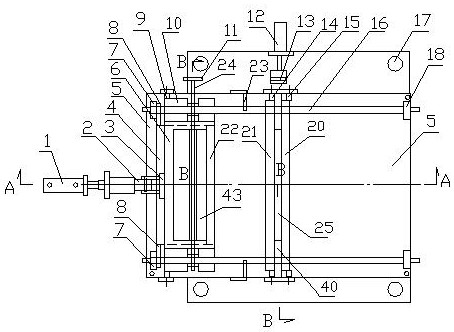
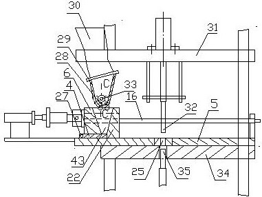
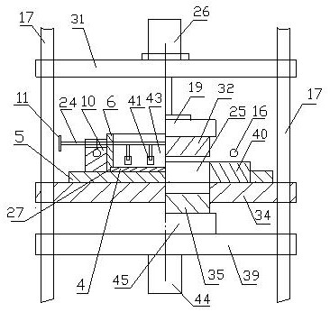
[0017] In the figure, a kind of powder strip non-destructive numerical control hydraulic press, it comprises frame, hydraulic system, controller and the feeding mechanism that fits on the frame, described frame is provided with upper template 31, middle template 34 and The lower formwork 39, the upper formwork, the middle formwork and the lower formwork are movably connected with four columns 17. The upper formwork is provided with an upper oil cylinder 26, and the upper oil cylinder 26 is connected with the upper punch seat 19 through a piston rod. The lower end of the punch seat 19 is connected with the upper punch 32, the lower template is provided with a lower oil cylinder 44, the lower oil cylinder is connected with the lower punch seat 45 through the piston rod, and the upper end of the lower punch seat is connected with the lower punch 35, The middle template is provided with a working plate 5, on which parallel guide shafts 16 are relatively arranged, and the two ends o...


PUM


Abstract

The invention discloses a nondestructive numerical control hydraulic machine for a powder strip. The machine comprises a machine frame, a hydraulic system, a controller and a feeding mechanism assembled on the machine frame, wherein an upper die plate, a middle die plate and a lower die plate are arranged on the machine frame, the upper die plate, the middle die plate and the lower die plate are movably connected through stand columns, a working plate is arranged on the middle die plate, guiding shafts are oppositely arranged on the working plate, the two ends of each guiding shaft are fixedlyarranged on supporting seats, shaft seats are movably arranged on the guiding shafts, a storage box capable of moving leftwards and rightwards in a horizontal direction of the working plate is fixedly connected between the shaft seats, a storage cavity is formed in the storage box, and an inserting plate is arranged between the lower bottom face of the storage box and the working plate. Accordingto the machine, it can be guaranteed that powder does not permeate into the surface of the working plate, the surface of the working plate and a die are not damaged, the service life of a model is prolonged, the quality of formed and pressed products is facilitated, and the powder can be accurately and rapidly injected into a forming cavity through the rotation number and rotation time and by using metering based on size, rotation number and time.

Description

technical field [0001] The invention relates to the technical field of powder injection molding hydraulics, in particular to a numerically controlled hydraulic machine for powder injection molding of long product parts. Background technique [0002] Powder injection molding technology (Powder Injection Molding, referred to as PIM) is an advanced near-net forming technology that introduces injection molding technology into powder metallurgy. PIM technology is used to manufacture small elongated parts in large quantities with hydraulic presses, which can solve the problem of traditional machinery. The manufacturing process faces problems such as large material consumption, many processing hours, unstable quality, and inability to form large batches. The use of PIM technology to manufacture long and small small parts in large quantities can greatly reduce the processing steps, the material utilization rate can reach 99%, reduce the processing cost, and improve the product accur...

Claims


Application Information

Patent Timeline
Patent Type & Authority Applications(China)
IPC IPC(8): B30B1/32B30B15/02B30B15/30
CPCB30B1/32B30B15/02B30B15/302
Inventor 黄静黄良以
Owner 黄静
Why Eureka
Try Eureka