
A time axis unified system and method

A unified method and time axis technology, applied to electronic timers, radio-controlled timers, clocks driven by synchronous motors, etc., can solve problems affecting positioning accuracy and data immediacy, and achieve the goal of improving accuracy Effect

Active Publication Date: 2022-04-05
上海感探号信息科技有限公司
View PDF8 Cites 0 Cited by
  • Summary
  • Abstract
  • Description
  • Claims
  • Application Information

AI Technical Summary

Problems solved by technology

[0003] Existing car positioning methods usually use a combination of multiple positioning methods to improve the accuracy of positioning. However, when combining multiple positioning methods, the existing car positioning methods usually need to build a multi-layer protocol for underlying device data interaction. , leading to a decrease in the immediacy of the data, and when the car is positioned, the car is often in motion, and the data of the moving car may change at any time, resulting in the integration of data at different times during data integration, which affects positioning the accuracy of

Method used


Image

  • A time axis unified system and method
  • A time axis unified system and method
  • A time axis unified system and method

Examples


Embodiment 1

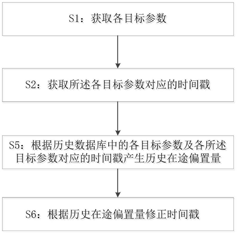
[0037] This embodiment provides a method for unifying the time axis, including:

[0038] S1: Obtain each target parameter of vehicle operation;

[0039] S2: Obtain the time stamp corresponding to each target parameter;

[0040] S5: Generate historical in-transit offsets according to the parameters stored in the historical database and the time stamps corresponding to the parameters;

[0041] S6: Correct the time stamp according to the historical in-transit offset.

[0042] in such as figure 1 As shown, in this embodiment, no matter whether it is a wheel, a satellite, a radar, a wireless or other sensing means, the frequency of collecting data is different, and the paths, formats, and protocols of data communication are different, and the communication needs Time will cause time deviation, and for a moving vehicle, time error is spatial position error. This error can be corrected and must be corrected before mutual coupling.

[0043]According to each described target param...

Embodiment 2

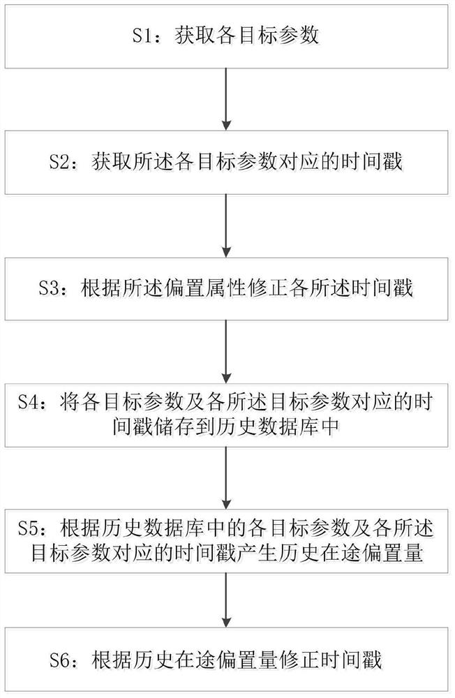
[0046] like figure 2 As shown, this embodiment provides a method for unifying the time axis, including:

[0047] S1: Obtain each target parameter of vehicle operation;

[0048] S2: Obtain the time stamp corresponding to each target parameter;

[0049] S3: Modify each of the timestamps according to the offset attribute;

[0050] S4: storing each of the target parameters and the time stamp corresponding to each of the target parameters in a historical database;

[0051] S5: Generate historical in-transit offsets according to the parameters stored in the historical database and the time stamps corresponding to the parameters;

[0052] S6: Correct the time stamp according to the historical in-transit offset.

[0053] In this embodiment, whether it is a wheel, satellite, radar, wireless or other sensing test means, when measuring the position of the vehicle, it is necessary to sample and modulate the measured state, that is, the spatial position, into at least one pulse Energ...

Embodiment 3

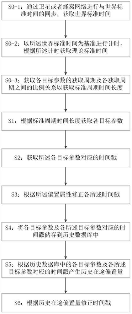
[0058] This embodiment provides a method for unifying the time axis, including:

[0059] S0-1: Obtain the universal time by synchronizing with the universal time through one or more of satellite or cellular network;

[0060] S0-2: Timing is performed based on the universal standard time, and a theoretical standard time is obtained according to the timing;

[0061] S1: Obtain each target parameter of vehicle operation;

[0062] S2: Obtain the time stamp corresponding to each target parameter according to the theoretical standard time;

[0063] S3: Modify each of the timestamps according to the offset attribute;

[0064] S4: storing each of the target parameters and the time stamp corresponding to each of the target parameters in a historical database;

[0065] S5: Generate historical in-transit offsets according to the parameters stored in the historical database and the time stamps corresponding to the parameters;

[0066] S6: Correct the time stamp according to the histor...


PUM


Abstract

The invention discloses a time axis unified system, comprising: a sensor module, used to obtain various target parameters of vehicle operation; the sensor module includes a variety of sensors; a clock module, used to perform time stamp processing on each target parameter; the clock module includes The in-transit offset correction sub-module; the in-transit offset correction sub-module includes a historical database and an in-transit offset correction unit. The target parameters and the time stamps corresponding to each target parameter are recorded in the historical database. The in-transit offset correction unit The time stamp corresponding to the parameter generates the historical in-transit offset, and the corresponding target parameter is corrected according to the historical in-transit offset. A time axis unification method is also disclosed. The technical effect of the present invention: the in-transit offset value is integrated through the historical data, so that the positioning parameters can be coupled and calculated according to the time stamp, so as to avoid the integration of data at different times, which is conducive to improving the accuracy of vehicle positioning.

Description

technical field [0001] The invention relates to the field of time service, in particular to a time axis unification system and method. Background technique [0002] Vehicle positioning refers to the application of global positioning system in vehicle management. There are many existing vehicle positioning methods, such as satellite positioning system, wireless communication positioning, radar ranging and speed measuring positioning, vehicle speed measurement positioning and axle load, fixed time position Determination etc. Among them, the satellite positioning system includes GPS / BD positioning satellites, roadside ground differential stations and vehicle-mounted terminals. This system realizes the positioning of vehicle-mounted terminals distributed in a wide area of ​​the city between multiple satellites and terminals. It is one of the traditional positioning methods. The wireless communication positioning system includes roadside wireless network base stations and vehicl...

Claims


Application Information

Patent Timeline
Patent Type & Authority Patents(China)
IPC IPC(8): G04R20/02G04R20/14G04G7/00G06F16/24
CPCG04R20/02G04R20/14G04G7/00G06F16/24
Inventor 曹春耕
Owner 上海感探号信息科技有限公司
Learn More