
Ceramic vacuum pump

A ceramic vacuum and pump casing technology, applied in the direction of pumps, pump devices, pump components, etc., can solve problems such as poor heat dissipation performance, and achieve the effects of reducing vibration, increasing service life, and good insulation performance

Active Publication Date: 2021-02-12
刘继刚 +1
View PDF7 Cites 0 Cited by
  • Summary
  • Abstract
  • Description
  • Claims
  • Application Information

AI Technical Summary

Problems solved by technology

[0005] The purpose of the present invention is to solve the problem of poor heat dissipation performance in the prior art, and the proposed ceramic vacuum pump

Method used


Image

  • Ceramic vacuum pump
  • Ceramic vacuum pump
  • Ceramic vacuum pump

Examples


Embodiment 1

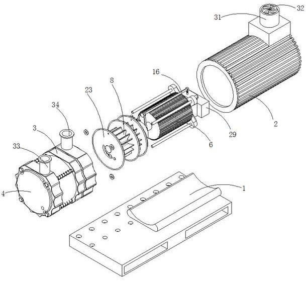
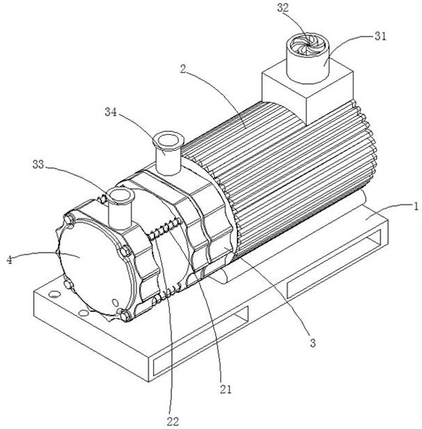
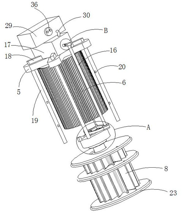
[0032] refer to Figure 1-6 , a ceramic vacuum pump, including a base 1, a pump casing and a motor casing 2, the pump casing and the motor casing 2 are sequentially arranged on the top of the base 1 along the horizontal direction, the pump casing includes a casing 3 and a casing cover 4, and the pump casing 3 The inner wall of the shell and the inner end surface of the shell cover 4 are sprayed with a ceramic coating with a thickness of 0.3 mm to 0.5 mm. The shell cover 4 is detachably connected to the opening of the shell 3 away from the motor shell 2. The shell 3 and the motor shell 2 are fixedly connected, the drive motor 6 is installed in the motor shell 2 through the X-shaped bracket 5, the drive end of the drive motor 6 is connected with the drive shaft 7, and the end of the drive shaft 7 away from the drive motor 6 extends to the inner cavity of the shell 3, and the transmission The extension end of the shaft 7 is eccentrically arranged in the inner cavity of the casing...

Embodiment 2

[0042] refer to Figure 1-2 , a ceramic vacuum pump, which is basically the same as in Embodiment 1, furthermore, the shell cover 4 and the shell 3 are provided with threaded mounting holes that cooperate with each other, and the threaded mounting holes on the shell 3 are threadedly connected with a connecting rod 21, and the connecting rod 21 The end away from the housing 3 is threadedly connected to the housing cover 4, and a tension spring 22 sleeved on the outer wall of the connecting rod 21 is fixedly connected between the housing 3 and the housing cover 4. The tension spring 22 helps to reduce the vacuum pump when it is working. vibration, while improving the tightness of the connection between the case cover 4 and the housing 3 .


PUM


Abstract

The invention discloses a ceramic vacuum pump. The ceramic vacuum pump comprises a base, a pump shell and a motor shell, wherein the pump shell and the motor shell are sequentially arranged at the topof the base in the horizontal direction, the pump shell comprises a shell body and a shell cover, the shell cover is detachably connected to an opening, away from the motor shell, of the shell body,the shell body is fixedly connected with the motor shell, a driving motor is installed in the motor shell through an X-shaped support, the driving end of the driving motor is connected with a transmission shaft, the end, away from the driving motor, of the transmission shaft extends into an inner cavity of the shell body, the extending end of the transmission shaft is eccentrically arranged in theinner cavity of the shell body and connected with an impeller, the side, away from the shell cover, of the shell body is rotationally connected with a driven belt wheel arranged in an inner cavity ofthe motor shell, the part, located in the motor shell, of the shaft wall of the transmission shaft is sleeved with a transmission belt wheel, and the side, away from the shell cover, of the shell body is further fixedly connected with a mounting base. According to the ceramic vacuum pump, a shock absorption function of the vacuum pump is achieved, meanwhile, a good heat dissipation function is achieved, the hardness of a ceramic coating is improved, the ceramic coating is more resistant to abrasion, high temperature and corrosion, and the service life is prolonged by 4 times to 5 times.

Description

technical field [0001] The invention relates to the technical field of vacuum pumps, in particular to ceramic vacuum pumps. Background technique [0002] A vacuum pump refers to a device or device that uses mechanical, physical, chemical or physicochemical methods to evacuate the evacuated container to obtain a vacuum. Generally speaking, a vacuum pump is a device that uses various methods to improve, generate and maintain vacuum in a certain closed space. [0003] According to the working principle of vacuum pumps, vacuum pumps can basically be divided into two types, namely gas capture pumps and gas transfer pumps. It is widely used in metallurgy, chemical industry, food, electronic coating and other industries. [0004] The disadvantage of the current vacuum pump is that the disadvantage of the vacuum pump is that it is prone to vibration during work, and the heat dissipation is not good, which not only affects the service life of the vacuum pump, is prone to failure, b...

Claims


Application Information

Patent Timeline
IPC IPC(8): F04D25/08F04D29/40F04D29/02F04D29/58F04D29/66H02K9/20H02K9/193H02K9/04
CPCF04D25/082F04D29/403F04D29/023F04D29/5806F04D29/5846F04D29/584F04D29/668H02K9/20H02K9/193H02K9/04F05D2300/20F05D2300/611F05D2300/506
Inventor 苏方宁
Owner 刘继刚
Learn More