TFT-LCD liquid crystal glass thickness adjusting device and use method thereof

A liquid crystal glass, thickness adjustment technology, applied in glass molding, glass molding, glass manufacturing equipment, etc., can solve the problems of temperature drop, rise, uneven thickness, etc., and achieve the effect of convenient disassembly and assembly

Pending Publication Date: 2021-02-12
RAINBOW (HEFEI) LIQUID CRYSTAL GLASS CO LTD
View PDF7 Cites 0 Cited by
  • Summary
  • Abstract
  • Description
  • Claims
  • Application Information

AI Technical Summary

Problems solved by technology

[0003] The existing technology has the following problems: in the process of glass liquid flowing through the side of the overflow brick to form liquid crystal glass, uneven thickness will be formed in the non-flow direction of the liquid crystal glass, resulting in differences in the thickness of the liquid crystal glass, thereby affecting product quality. In the device, there is a section of blowing box at the bottom of the overflow brick tip, blowing the inner surface of the box with compressed air to reduce the temperature of the inner surface of the box, and adjusting the cooling rate of the liquid crystal glass by blowing the temperature of different parts of the box. Speed, so as to achieve the purpose of adjusting the thickness of the glass. In normal production, some parts of the liquid crystal glass cannot achieve the purpose of adjusting the glass thickness by simply cooling down with compressed air. On the contrary, it is necessary to increase the temperature to change the thickness of the liquid crystal glass to meet the production process requirements.

Method used


Image

  • TFT-LCD liquid crystal glass thickness adjusting device and use method thereof
  • TFT-LCD liquid crystal glass thickness adjusting device and use method thereof
  • TFT-LCD liquid crystal glass thickness adjusting device and use method thereof

Examples


Embodiment Construction

[0031] The following will clearly and completely describe the technical solutions in the embodiments of the present invention with reference to the accompanying drawings in the embodiments of the present invention. Obviously, the described embodiments are only some, not all, embodiments of the present invention. Based on the embodiments of the present invention, all other embodiments obtained by persons of ordinary skill in the art without making creative efforts belong to the protection scope of the present invention.

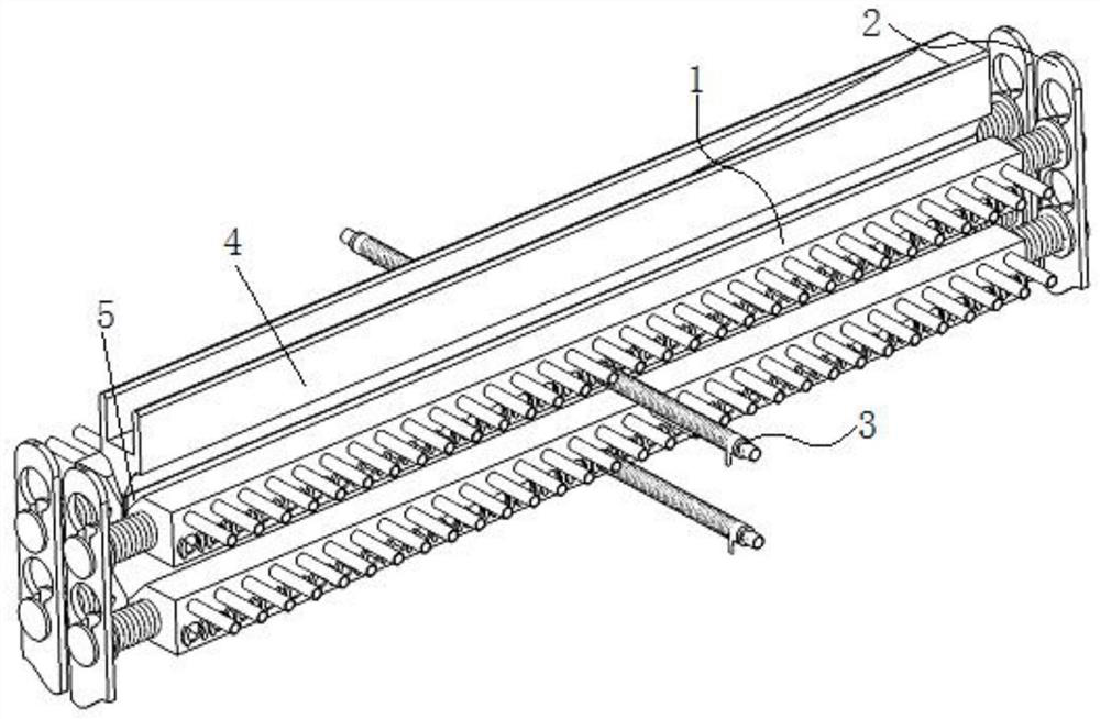
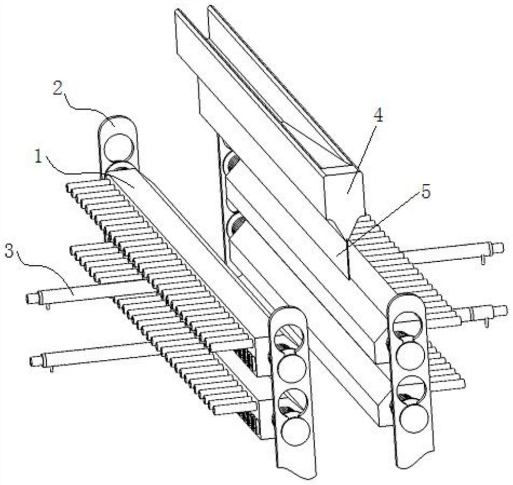
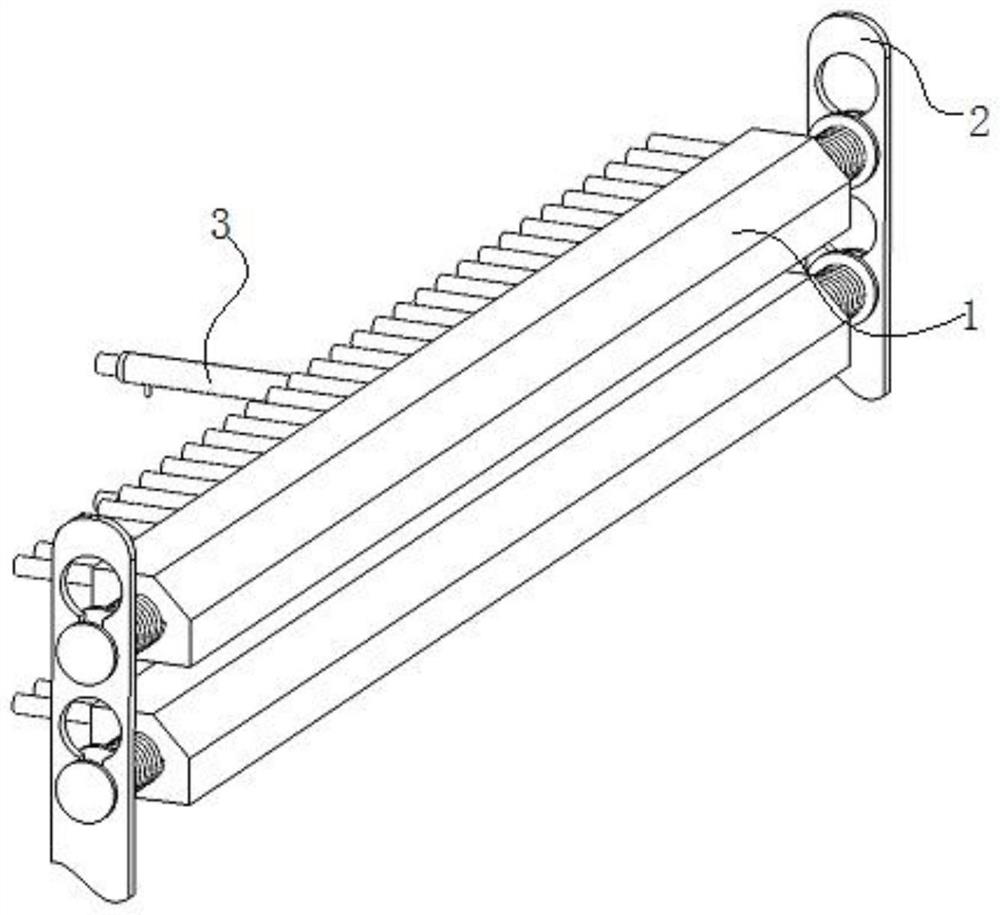
[0032] see Figure 1-9 , the present invention provides the following technical solutions: a device for adjusting the thickness of TFT-LCD liquid crystal glass, including multiple groups of hollow blowing box assemblies 1, the two ends of the hollow blowing box assemblies 1 are tightly inserted on the mounting frame plate assembly 2, and the hollow Multiple groups of blowing pipe assemblies 3 are clamped on the rear side of the blowing box assembly 1, and the ...


PUM


Abstract

The invention discloses a TFT-LCD liquid crystal glass thickness adjusting device which comprises a plurality of hollow air blowing box assemblies, the two ends of each hollow air blowing box assemblyare arranged on a mounting frame plate assembly in an abutting and inserting mode, and a plurality of air blowing pipe assemblies are arranged on the box body on the rear side face of each hollow airblowing box assembly in a clamped mode. The multiple sets of air blowing pipe assemblies are arranged on the box body on the rear side face of the hollow air blowing box assembly in a row structure,the multiple sets of hollow air blowing box assemblies are installed in a pairwise opposite mode, and a heating gap allowing liquid crystal glass formed in an overflow brick in a downward flowing modeto flow through is formed between every two opposite sets of hollow air blowing box assemblies. The box body on the inner side surface of the hollow air blowing box assembly heats the liquid crystalglass in a contact manner, and the air blowing pipe assembly enters the hollow air blowing box assembly to adjust the surface temperature of the inner layer of the hollow air blowing box assembly; thetemperature of the liquid crystal glass is changed by changing the temperature of the inner surface of the hollow air blowing box assembly with good thermal conductivity, so that the cooling speed ofthe liquid crystal glass is changed.

Description

technical field [0001] The invention belongs to the technical field of liquid crystal glass substrate processing and manufacturing, and in particular relates to a device and method for adjusting the thickness of a TFT-LCD liquid crystal glass. Background technique [0002] In the production process of TFT-LCD liquid crystal glass overflow down-drawing method, after the liquid crystal glass flows out from the inner groove of the overflow brick, it is bonded on the side of the overflow brick to form a liquid crystal glass substrate with the width and thickness required by the process. [0003] The existing technology has the following problems: in the process of glass liquid flowing through the side of the overflow brick to form liquid crystal glass, uneven thickness will be formed in the non-flow direction of the liquid crystal glass, resulting in differences in the thickness of the liquid crystal glass, thereby affecting product quality. In the device, there is a section of ...

Claims


Application Information

Patent Timeline
Patent Type & Authority Applications(China)
IPC IPC(8): C03B17/06
CPCC03B17/064C03B17/068C03B17/067
Inventor 郭军利赵亮李继彬
Owner RAINBOW (HEFEI) LIQUID CRYSTAL GLASS CO LTD
Why Eureka
Try Eureka