A drill press capable of automatic cleaning and chip removal

An automatic cleaning and drilling machine technology, which is applied in the field of drilling machines, can solve the problems of consuming a lot of human resources, troublesome cleaning, and accumulation of waste debris, etc., so as to avoid machine wear and increase in use costs, and is conducive to long-term work and high-efficiency of the machine The effect of efficient production

Active Publication Date: 2022-01-11
杭州力云机械有限公司
View PDF11 Cites 0 Cited by
  • Summary
  • Abstract
  • Description
  • Claims
  • Application Information

AI Technical Summary

Problems solved by technology

[0005] The technical problem to be solved by the present invention is to provide a drilling machine capable of automatic cleaning and chip removal. One of the purposes is to provide a support plate and a dust suction fan to solve the problem of the accumulation of waste chips generated when the drilling machine is drilling and tapping. It causes troublesome cleaning and consumes a lot of human resources; another purpose is to solve the problem that too much waste and not cleaned up in time will cause the internal gap parts of the machine to enter the waste and cause damage to the machine, so as to achieve the goal of drilling and tapping on the drilling machine. While the wire is working, it can effectively clean up the waste to achieve the effect of convenient production work. Another purpose is to have a cooling chamber, which is convenient for the machine to provide effective cooling when it is running, which is conducive to the long-term work and high-efficiency of the machine. Production, solves the problem that the temperature of the machine rises too fast and the heat dissipation effect is poor because of the need for multiple tasks such as automatic chip removal at the same time, which easily causes the problem of the machine being burned due to high temperature

Method used


Image

  • A drill press capable of automatic cleaning and chip removal
  • A drill press capable of automatic cleaning and chip removal
  • A drill press capable of automatic cleaning and chip removal

Examples


Embodiment 1

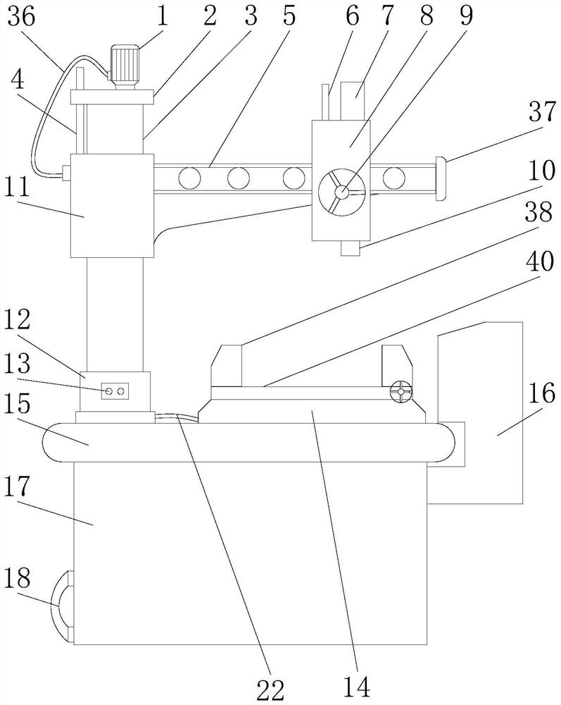
[0031] Such as Figure 1-Figure 6 As shown, the present invention provides a drilling machine capable of automatic cleaning and chip removal. The heat dissipation chamber 15 has a condenser 33 fixedly installed on the inner bottom of the heat dissipation chamber 15, and a compressor 34 is fixedly installed on the front of the condenser 33. The condenser 33 Condenser tubes 32 are evenly and fixedly connected to both sides of the heat sink 15, and the bottom of the heat dissipation chamber 15 is fixedly equipped with a chip box 17, and the inner top of the chip box 17 is fixedly installed with a hanger 25, and the bottom of the hanger 25 is fixedly installed with a turbine 26, and the turbine The bottom of 26 is movably equipped with rotating shaft 27, and the outer wall of rotating shaft 27 is evenly provided with dust suction fan 28.

[0032] In this embodiment, a condenser 33, a compressor 34 and a plurality of condensation pipes 32 are provided inside the cooling chamber 15 ...

Embodiment 2

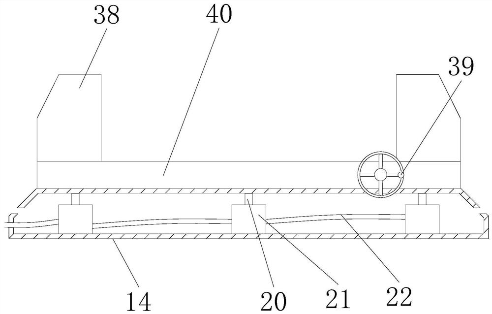
[0036] Such as figure 1 , figure 2 , image 3 , Figure 4 , Figure 5As shown, on the basis of Embodiment 1, the present invention provides a technical solution: a support plate 14 is fixedly installed on the top of the cooling chamber 15, which mainly acts on the support fixture 38, and the inner top of the support plate 14 is fixedly installed There is a beam 20, which is mainly used for supporting and weighing. The bottom of the beam 20 is fixed with a scale base 21, which is mainly used for weighing and inductive transmission. The outer wall of the scale base 21 is fixedly connected with a transmission line 22, which is mainly used for transmission. , the transmission line 22 extends to the left and is fixedly connected with the controller 12, which is mainly used to control the vacuuming of the dust collection fan 28. The surface of the cooling chamber 15 is penetrated with a control line 24, and the top of the control line 24 is fixedly connected with the controller ...

Embodiment 3

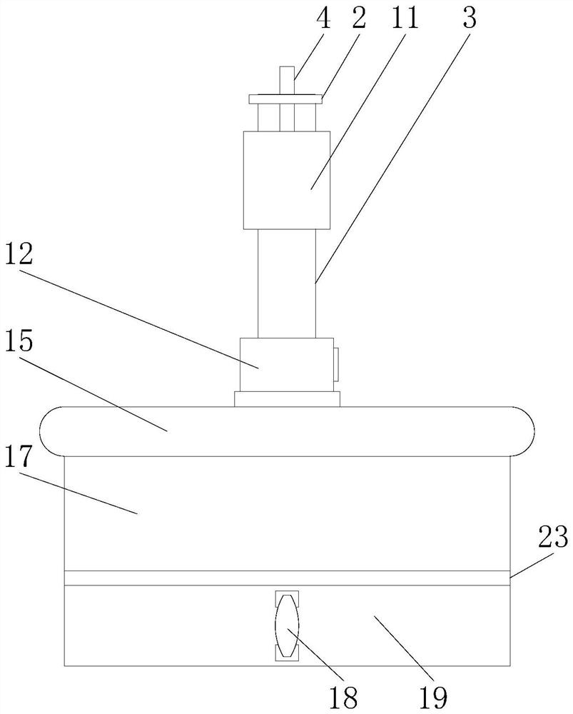
[0038] Such as figure 1 , figure 2 , Figure 4 , Figure 5 As shown, on the basis of Embodiment 1 and Embodiment 2, the present invention provides a technical solution: the bottom of the inner side of the dust collection box 17 is provided with a slideway-31, which is mainly used to facilitate sliding, and the top of the slideway-31 A pulley 30 is provided, which is mainly used to facilitate sliding. The top of the pulley 30 is fixed with a drawer 19, which is mainly used for loading waste and can be replaced quickly. The left side of the drawer 19 is fixed with a handle 18, which is mainly used for pulling. Drawer 19, the top left side of drawer 19 is provided with sealing strip 23, and it is mainly used in sealing, and the top of cooling bin 15 is fixedly installed with controller 12, and the front of controller 12 is fixedly installed with control button 13, and it mainly acts on control. To operate the machine, the right side of the controller 12 is fixedly connected w...


PUM


Abstract

The invention discloses a drilling machine capable of automatic cleaning and chip removal, which relates to the technical field of drilling machines, and comprises a heat dissipation chamber, a condenser is fixedly installed on the inner bottom of the heat dissipation chamber, a compressor is fixedly installed on the front of the condenser, two sides of the condenser Uniform fixed connection with condenser tube. The present invention uses the combination of the support plate and the dust suction fan to facilitate weighing sensing by using the scale beam and the scale base inside the support plate. Whenever the top of the support plate reaches a certain weight, the induction device inside the scale base passes Transmission information, command controller to control the vacuum fan to automatically vacuum dust and debris, avoiding a lot of debris during processing, using the combination of heat dissipation chamber and condenser to realize condensation inside the heat dissipation chamber when the drilling machine is running The machine provides low temperature, and the condensing pipe drives the condensate to circulate to provide effective heat dissipation and cooling for the drilling machine, which is conducive to the long-term work of the machine and high-efficiency production.

Description

technical field [0001] The invention relates to a drilling machine, and relates to the technical field of automatic cleaning and chip removal of the drilling machine, in particular to a drilling machine capable of automatic cleaning and chip removal. Background technique [0002] Drilling machine refers to a machine tool that mainly uses a drill bit to process holes in a workpiece. Generally, the rotation of the drill bit is the main movement, and the axial movement of the drill bit is the feed movement. The drilling machine has a simple structure and relatively low machining accuracy. It can drill through holes and blind holes, replace special tools, expand, countersink, ream or tap. During the machining process, the workpiece does not move, let the tool move, align the center of the tool with the center of the hole, and rotate the tool. The characteristic of the drilling machine is that the workpiece is fixed and the tool rotates. Drilling machine is a general-purpose m...

Claims


Application Information

Patent Timeline
Patent Type & Authority Patents(China)
IPC IPC(8): B23P23/02B23B39/00B23Q11/12B23Q11/00B08B5/04
CPCB23P23/02B23B39/00B23Q11/12B23Q11/0046B08B5/04
Inventor 徐忠林
Owner 杭州力云机械有限公司
Why Eureka
Try Eureka