
Stamping die with double-cooling type forming punch

A technology for forming punches and stamping dies, applied in forming tools, manufacturing tools, metal processing equipment, etc., can solve problems such as unfavorable product cooling, damage to the quality of formed products, and inability to disperse, so as to improve the cooling effect and enhance cooling effect, the effect of rapid cooling

Inactive Publication Date: 2021-02-12
王凯
View PDF0 Cites 2 Cited by
  • Summary
  • Abstract
  • Description
  • Claims
  • Application Information

AI Technical Summary

Problems solved by technology

[0003] The punch is one of the essential components in the stamping die. It undertakes punching, internal splines and other processes during the entire stamping forming process. A large amount of heat will be generated during the stamping process, and the punch is directly connected with the finished product. Contact is not conducive to the cooling of the product during the hot stamping process. When there is a large amount of heat, it is difficult to quickly dissipate it, resulting in damage to the quality of the formed product

Method used


Image

  • Stamping die with double-cooling type forming punch
  • Stamping die with double-cooling type forming punch
  • Stamping die with double-cooling type forming punch

Examples


Embodiment 1

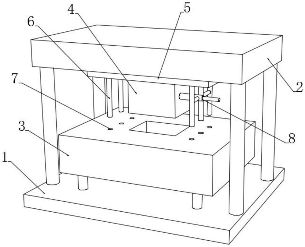
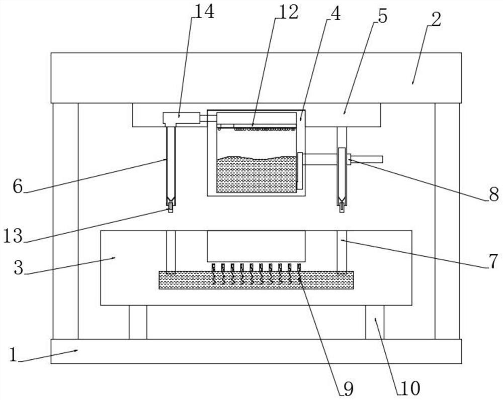
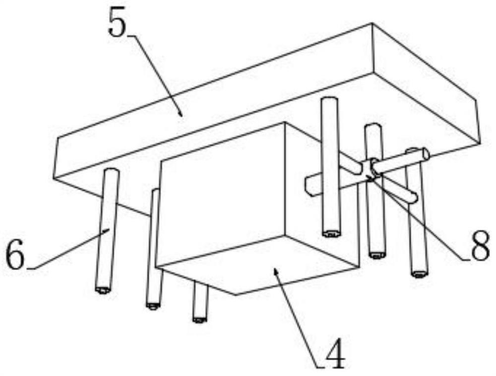
[0046] see Figure 1-4 , a stamping die with a double-cooled forming punch, including a lower mold base 1 and an upper mold base 2 fixedly arranged up and down, and a core 3 is fixedly connected to the lower mold base 1 through a plurality of electric telescopic cylinders 10 , the bottom end of the upper mold base 2 is fixedly connected with a punch 4 that matches the core 3 through a punch 4, and the core 3 is provided with a cavity that matches the punch 4, and the punch 4 There are a plurality of air-supply guide columns 6 distributed on both sides of the lower end, and a plurality of air-supply guide columns 6 are provided on both sides of the upper end of the core 3. Guide cavities 7 corresponding to the positions of the air-supply guide columns 6 are arranged. Die and mold opening play a guiding role. The inner bottom of the core 3 is provided with a lower cooling chamber connected to the bottom ends of a plurality of guide chambers 7. The inside of the punch 4 is provid...


PUM


Abstract

The invention discloses a stamping die with a double-cooling type forming punch, and belongs to the technical field of stamping. The stamping die is characterized in that an upper cooling cavity and alower cooling cavity filled with cooling liquid are arranged in a mold core and the punch respectively, and the upper cooling cavity and the lower cooling cavity communicate with each other through symmetrically-arranged air supply guide columns; air circularly flows between the upper cooling cavity and the lower cooling cavity through the air supply guide columns, and matching of air cooling andwater cooling is achieved, so that the cooling effect on the die is effectively improved; in addition, a magnetic attraction plate is arranged inside the punch, the bottom end of the magnetic attraction plate magnetically attracts a plurality of magnetic nitratine particles, after die assembly, water-soluble magnetism-starting trigger bodies located at the bottom ends of the air supply guide columns disintegrate when meeting water to trigger an on-off switch of the magnetic attraction plate, after the magnetic attraction plate is powered off, the plurality of magnetic nitratine particles fallinto the cooling liquid in the upper cooling cavity, and the cooling liquid is gradually cooled and partially frozen when meeting the magnetic nitratine particles; and on one hand, the cooling effectof the punch on the die is directly improved, on the other hand, a cooling effect on the circularly flowing air is achieved, and rapid cooling of the die is achieved.

Description

technical field [0001] The invention relates to the technical field of stamping, and more specifically relates to a stamping die with a double-cooled forming punch. Background technique [0002] Molds, various molds and tools used in industrial production for injection molding, blow molding, extrusion, die-casting or forging forming, smelting, stamping and other methods to obtain the required products. Molds are tools used to make shaped objects. Among them, the hot stamping forming technology in the stamping die is to heat the steel plate to the austenitic state, then stamp it and quench it at a fast cooling rate at the same time to obtain a high-strength steel member with a uniform martensitic structure. [0003] The punch is one of the essential components in the stamping die. It undertakes punching, internal splines and other processes during the entire stamping forming process. A large amount of heat will be generated during the stamping process, and the punch is direct...

Claims


Application Information

Patent Timeline
IPC IPC(8): B21D37/16B21D37/10B21D22/02
CPCB21D22/02B21D37/10B21D37/16
Inventor 王凯
Owner 王凯
Learn More