
Shield tunneling machine muck improvement method

A technology of muck improvement and shield machine, which is applied in the direction of earth square drilling, mining equipment, tunnels, etc., which can solve the problems of easy generation of mud cake, difficult treatment, and ineffective improvement of dregs, so as to improve the scouring capacity and ensure effect of effect

Active Publication Date: 2021-02-09
ROAD & BRIDGE SOUTH CHINA EINGINEERING CO LTD +1
View PDF5 Cites 1 Cited by
  • Summary
  • Abstract
  • Description
  • Claims
  • Application Information

AI Technical Summary

Problems solved by technology

However, in complex formations such as mudstone, argillaceous siltstone, viscous dehydration, and uneven hardness and softness, due to the influence of geology and hydrology, the rock blocks become debris and powder under the cutting of the tool and the impact of the cutterhead. The improvement effect of the muck at the center opening of the cutter head is poor, and the phenomenon of mud cake is easy to occur under the extrusion condition of the cutter head rotation and high temperature
At the same time, according to the construction test results of the existing shield machine, when the blocking pressure at the injection port is greater than the pressure injection resistance, the pipeline is basically in a blocked state, and the pressure injection of the modifier cannot be performed, resulting in the muck being unable to be effectively improved , it is easy to cause blockage in the soil silo and produce mud cake, etc.
However, it is difficult to completely prevent the mud cake at the center of the cutter head by using the conventional muck improvement system. When the mud cake is formed at the center of the cutter head, it is extremely difficult to handle, and the mud cake formed in the center will speed up the rapid recovery of the mud cake in the soil bin and the cutter head. formation, seriously affecting the normal construction of the shield machine

Method used


Image

  • Shield tunneling machine muck improvement method
  • Shield tunneling machine muck improvement method
  • Shield tunneling machine muck improvement method

Examples


Embodiment Construction

[0045] Embodiments of the present invention are described in detail below, and examples of the embodiments are shown in the drawings, wherein the same or similar reference numerals denote the same or similar elements or elements having the same or similar functions throughout. The embodiments described below by referring to the figures are exemplary only for explaining the present invention and should not be construed as limiting the present invention.

[0046] Those skilled in the art will understand that unless otherwise stated, the singular forms "a", "an", "said" and "the" used herein may also include plural forms. It should be further understood that the word "comprising" used in the description of the present invention refers to the presence of features, integers, steps, and operations, but does not exclude the existence or addition of one or more other features, integers, steps, and operations.

[0047] Those skilled in the art can understand that, unless otherwise defi...


PUM


Abstract

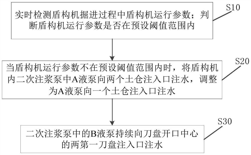
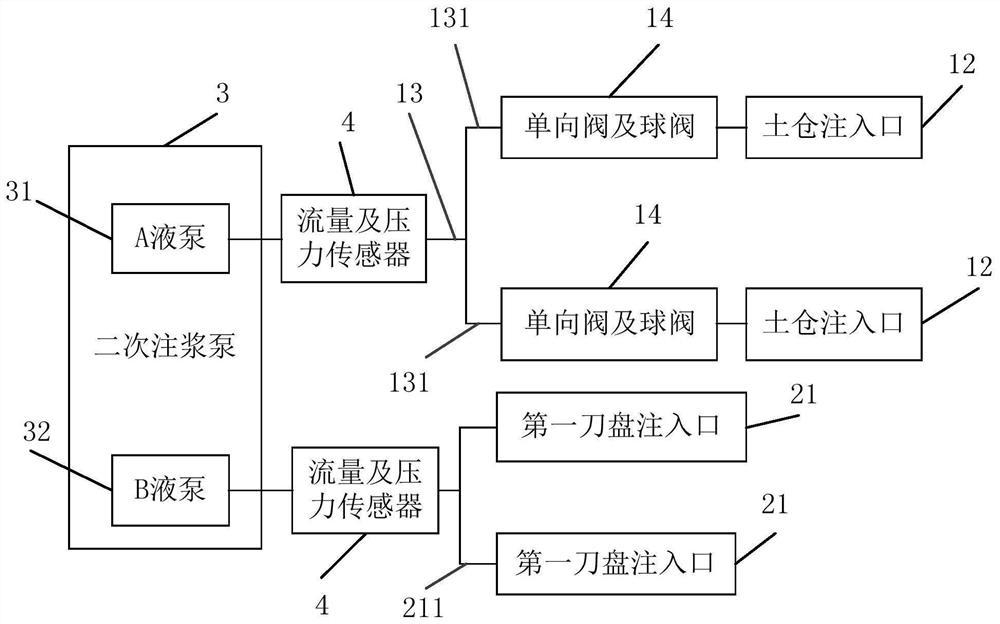
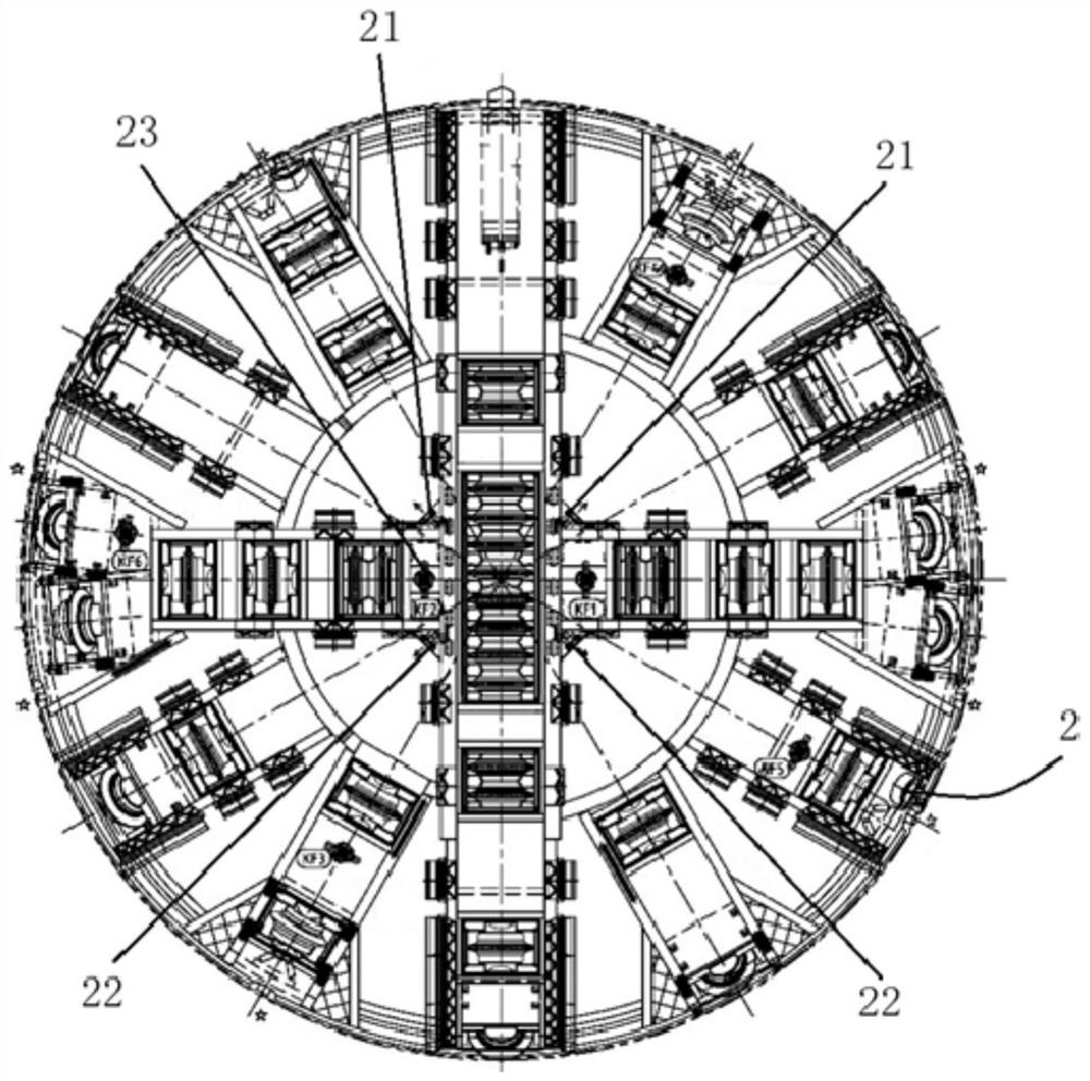
The invention relates to a shield tunneling machine muck improvement method. The method comprises the steps that shield tunneling machine operation parameters in the tunneling process of a shield tunneling machine are detected in real time; whether the shield tunneling machine operation parameters are within a preset threshold range or not is judged; when the shield tunneling machine operation parameters are not within the preset threshold range, the situation that a liquid pump A in a secondary grouting pump in the shield tunneling machine injects water into two or more soil bin injection ports is adjusted to the situation that the liquid pump A injects water into one soil bin injection port; and a liquid pump B in the secondary grouting pump continuously injects water into two first cutterhead injection ports in the center of a cutterhead opening. The secondary grouting pump is reasonably connected into the shield tunneling machine, and secondary grouting equipment in conventional shield tunneling construction is fully utilized. Due to the fact that the pump energy of the secondary grouting pump is large, the secondary grouting pump is adopted to inject water into an emergency standby injection port in the center of a soil bin wall plate and the injection port of the cutterhead opening, the scouring capacity to the center of the soil bin wall plate and the center opening of the cutterhead is improved, the injection ports are not prone to being blocked, and mud cakes are prevented from appearing in the center of the soil bin wall plate and the center of the cutterhead.

Description

technical field [0001] The invention relates to the technical field of shield machine construction, in particular to a method for improving dregs of a shield machine. Background technique [0002] Conventional dregs improvement methods are often used in the design and use of shield machines at home and abroad. The dregs improvement system is designed by using shield machines, and the cutter head or soil bin is improved by using foam, mud, water and other modifiers, which can basically be improved. Satisfy the muck improvement of the shield machine under weak and single geological conditions. However, in complex formations such as mudstone, argillaceous siltstone, viscous dehydration, and uneven hardness and softness, due to the influence of geology and hydrology, the rock blocks become debris and powder under the cutting of the tool and the impact of the cutterhead. The improvement effect of the muck at the center opening of the cutter head is poor, and the phenomenon of mu...

Claims


Application Information

Patent Timeline
IPC IPC(8): E21D9/06E21D9/08
CPCE21D9/0678E21D9/08
Inventor 王用斌刘伟邹进冲杨洪磊李则曦田浩
Owner ROAD & BRIDGE SOUTH CHINA EINGINEERING CO LTD
Learn More