Eureka AIR delivers breakthrough ideas for toughest innovation challenges, trusted by R&D personnel around the world.

Waterproof base surface coating device for road construction

A technology of road construction and coating equipment, which is applied in the direction of roads, roads, road repairs, etc., and can solve problems such as poor coating effect

Inactive Publication Date: 2021-02-09
李好宣
View PDF0 Cites 1 Cited by
  • Summary
  • Abstract
  • Description
  • Claims
  • Application Information

AI Technical Summary

Problems solved by technology

[0004] Based on the technical problem that the actual coating effect of the water release base surface coating is poor in the prior art, the present invention proposes a waterproof base surface coating device for road construction

Method used


Image

  • Waterproof base surface coating device for road construction
  • Waterproof base surface coating device for road construction
  • Waterproof base surface coating device for road construction

Examples


Embodiment 1

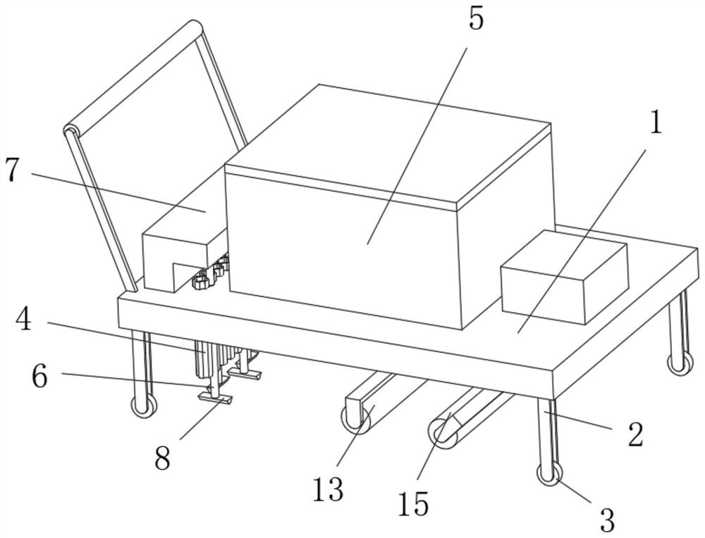
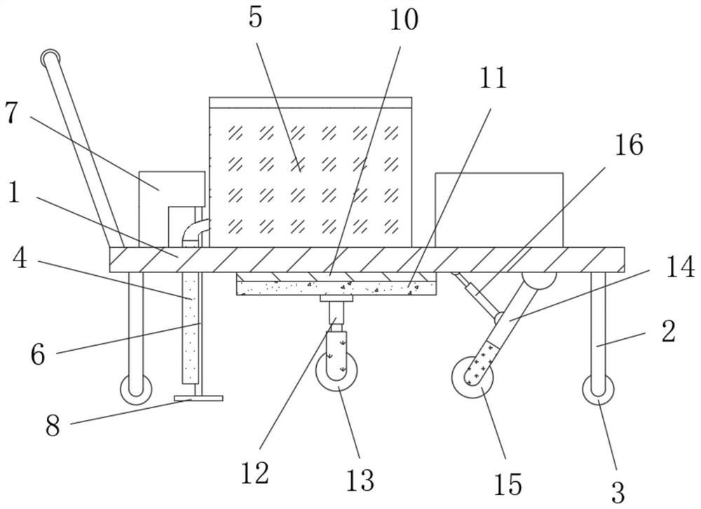
[0027] refer to Figure 1-4 , a waterproof base surface coating device for road construction, comprising a base 1, the four corners of the bottom of the base 1 are fixed with a support frame 2, and the bottom end of the support frame 2 is provided with a moving wheel 3, and the top of the base 1 A liquid tank 5 is fixed, and a plurality of coating pipes 4 are connected to the bottom of the liquid tank 5, a handrail is fixed on one side of the top of the base 1, and a coating roller 13 is arranged at the middle position of the bottom of the base 1, and a coating roller 13 is arranged on the top of the base 1. The side close to the handrail is provided with fixed grooves distributed equidistantly, and the coating pipe 4 is vertically fixed in the fixed groove, and the top of the base 1 is located on both sides of a plurality of coating pipes 4 and is connected with a plurality of connecting rods 6 in rotation. , and the connecting rods 6 located on both sides of the coating pipe...

Embodiment 2

[0033] refer to Figure 1-5 , a waterproof base surface coating device for road construction, a spring 17 is fixed on the outer wall of the positioning member 14 close to the electric telescopic rod 16, and the top of the spring 17 is fixedly connected to the bottom of the base 1, and the bottom of the base 1 is located at the positioning One side of member 14 away from spring 17 is rotatably connected with auxiliary frame 18 by torsion spring, and the bottom end of auxiliary frame 18 is rollingly connected with auxiliary ball 19, and the outer wall of auxiliary ball 19 is in contact with one side outer wall of positioning member 14.

[0034] During use, the auxiliary frame 18 connected with the spring 17 and the torsion spring reduces the vibration damage of the positioning member 14, thereby improving the actual use effect of the equipment.


PUM


Abstract

The invention belongs to the technical field of road construction, particularly relates to a waterproof base surface coating device for road construction, and provides the following scheme for solvingthe problem that in the prior art, the actual coating effect of waterproof base surface coating is poor: the waterproof base surface coating device comprises a base, supporting frames are fixed to the four corners of the bottom of the base, and moving wheels are arranged at the bottom ends of the supporting frames; a liquid tank is fixed to the top of the base, a plurality of coating pipes are connected to the bottom of the liquid tank, a handrail is fixed to one side of the top of the base, and a coating roller is arranged in the middle of the bottom of the base. According to the invention,the arc-shaped arching parts on the inner walls of the coating pipes are utilized to facilitate diffusion and falling of waterproof glue to the periphery, and the arc-shaped arching parts are matchedwith the connecting rods and the dispersing pieces distributed on the two sides of the plurality of coating pipes to rotate, so that the just falling waterproof glue is diffused into a plane, and thewaterproof glue guided by two adjacent coating pipes interacts, thereby reducing the thickness difference; therefore, the actual waterproof base surface coating effect is improved.

Description

technical field [0001] The invention relates to the technical field of road construction, in particular to a waterproof base surface coating device for road construction. Background technique [0002] Road engineering refers to the whole process of planning, design, construction, maintenance and management with roads as the object and the engineering entities involved. Like any other civil engineering, road engineering has obvious technical, economic and In terms of management characteristics, during the road construction process, it is often necessary to coat the base surface of the construction road with a waterproof base. [0003] Nowadays, when coating the waterproof base surface in the process of road construction, a mobile coating device is generally used. A storage mechanism filled with waterproof glue is arranged above the moving mechanism, and the waterproof glue flows downward through the coating pipe. On the pavement, the laying of waterproof glue on the road sur...

Claims


Application Information

Patent Timeline
IPC IPC(8): E01C19/16E01C19/48
CPCE01C19/16E01C19/4866
Inventor 李好宣
Owner 李好宣
Why Eureka
Eureka Blog
Learn More