
Quick forming and slitting integrated equipment for sintered brick production

A technology for sintered bricks and equipment, which is applied in the field of rapid prototyping and slitting integrated equipment for sintered brick production, can solve the problems of low productivity of sintered bricks, poor compactness of the green body, loss of water in the green body, etc., and achieves a smooth and uniform surface. Density, the effect of improving production efficiency

Active Publication Date: 2021-02-09
宜兴市鼎诚建筑陶瓷有限公司
View PDF5 Cites 0 Cited by
  • Summary
  • Abstract
  • Description
  • Claims
  • Application Information

AI Technical Summary

Problems solved by technology

In the prior art, most of the materials are mixed and formed, and then slitting is performed, which occupies the processing site and takes a long time to process, resulting in low productivity of sintered bricks.
In addition, in the production process, there will be phenomena such as poor compactness of the green body and uneven interior.
[0003] The invention provides a rapid prototyping and cutting integrated equipment for the production of sintered bricks, which realizes the cutting function while the green body is formed, and can also ensure the compactness and uniformity of a single divided body in this process, shortening the processing time, and It can take into account the production quality of sintered bricks, greatly improving the production efficiency of sintered bricks; in addition, it solves the problem of water loss and waste in the green body during the molding process

Method used


Image

  • Quick forming and slitting integrated equipment for sintered brick production
  • Quick forming and slitting integrated equipment for sintered brick production
  • Quick forming and slitting integrated equipment for sintered brick production

Examples


Embodiment Construction

[0029] The following will clearly and completely describe the technical solutions in the embodiments of the present invention with reference to the accompanying drawings in the embodiments of the present invention. Obviously, the described embodiments are only some, not all, embodiments of the present invention. Based on the embodiments of the present invention, all other embodiments obtained by persons of ordinary skill in the art without making creative efforts belong to the protection scope of the present invention.

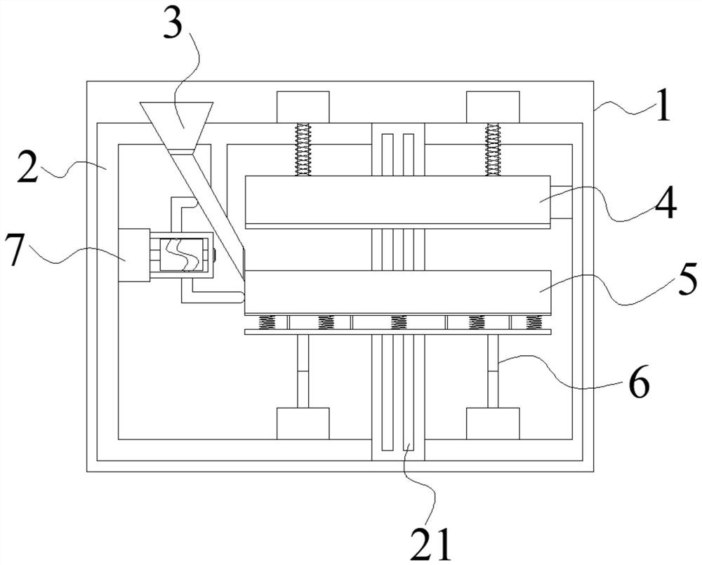
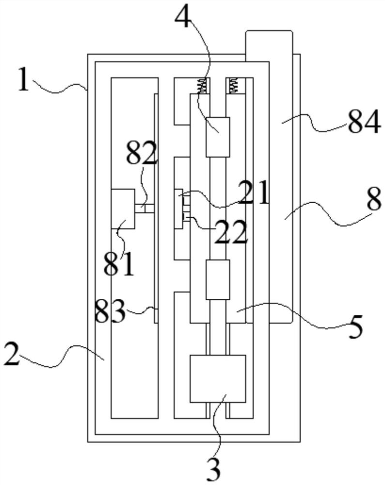
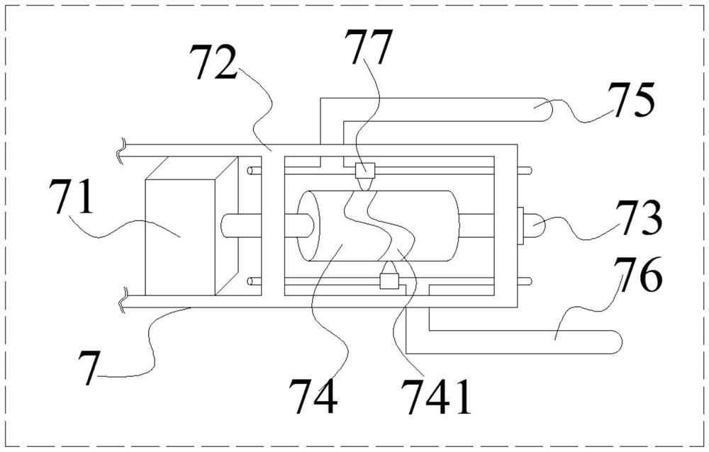
[0030] see Figure 1-6 , the present invention provides a technical solution: a rapid prototyping and cutting integrated equipment for sintered brick production, including a device body 1, a frame 2, a feeding mechanism 3, an extrusion molding mechanism 4, a mold cavity 5, a cutting mechanism 6, The shaking mechanism 7 and the feeding mechanism 8, the frame 2 is located inside the equipment body 1, the feeding mechanism 3 is fixedly welded on the frame 2, the ...


PUM


Abstract

The invention discloses quick forming and slitting integrated equipment for sintered brick production. The equipment comprises an equipment body, a rack, a feeding mechanism, an extrusion forming mechanism, a die cavity, a slitting mechanism, a shaking mechanism and supplying mechanisms, wherein the rack is located in the equipment body, the feeding mechanism is fixedly welded to the rack and is located on one side of the extrusion forming mechanism, the extrusion forming mechanism is arranged at the upper end of the rack, the die cavity is hollow and is fixed to the rack, the die cavity is formed right below the extrusion forming mechanism in a horizontal direction, the slitting mechanism is arranged right below the die cavity in parallel, the bottom end of the slitting mechanism is fixedly connected to the rack, one end of the shaking mechanism is fixed to the rack and the other end of the shaking mechanism is in contact with the feeding mechanism and the side wall of the die cavity,separately, the supplying mechanisms are distributed on two sides of the die cavity, the feeding mechanism comprises a feeding hopper, a feeding pipe and a spiral pipe, the feeding pipe is arranged obliquely, the upper end of the feeding pipe is connected to the bottom end of the feeding hopper, an opening in the other end of the feeding pipe is formed vertically, and the spiral pipe is arrangedin the feeding pipe in a penetrating manner.

Description

technical field [0001] The invention relates to the technical field of equipment for sintered brick production, in particular to a rapid prototyping and cutting integrated equipment for sintered brick production. Background technique [0002] The production of sintered bricks includes several major processes such as material mixing, green body forming, slitting, and firing, among which green body forming is a particularly critical step. In the prior art, most of the materials are mixed and formed, and then slitting is performed, which occupies the processing site and takes a long time to process, resulting in low productivity of sintered bricks. In addition, in the production process, there will be phenomena such as poor compactness of the green body and uneven interior. [0003] The invention provides a rapid prototyping and cutting integrated equipment for the production of sintered bricks, which realizes the cutting function while the green body is formed, and can also e...

Claims


Application Information

Patent Timeline
Patent Type & Authority Applications(China)
IPC IPC(8): B28B3/02B28B3/08B28B7/10B28B11/14B28B13/02B28B17/00
CPCB28B3/086B28B11/14B28B7/10B28B13/025B28B13/0235B28B3/022B28B17/00
Inventor 许诚杜建英霍鹏飞周泽荣贾芸李伟
Owner 宜兴市鼎诚建筑陶瓷有限公司
Learn More