A Time Error Correction Method Based on Distributed System
A distributed system and time error technology, applied in the direction of time division multiplexing system, transmission system, digital transmission system, etc., can solve the problems of non-uniform and non-standardized server time, improve work efficiency, reduce workload, Avoid Lost Effects
- Summary
- Abstract
- Description
- Claims
- Application Information
AI Technical Summary
Problems solved by technology
Method used
Image


Examples
Embodiment 1
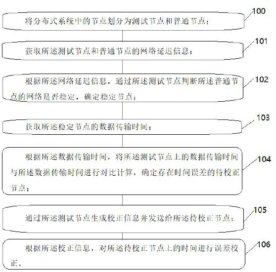
[0081] as attached figure 1 As shown, the present invention is a time error correction method based on a distributed system, comprising:
[0082] Step 100: Divide the nodes in the distributed system into test nodes and common nodes;
[0083] Step 101: Obtain the network delay information of the test node and the normal node;
[0084] Step 102: According to the network delay information, judge whether the network of the normal node is stable through the test node, and determine a stable node;
[0085] Step 103: Obtain the data transmission time of the stable node;
[0086] Step 104: According to the data transmission time, compare and calculate the data transmission time on the test node with the data transmission time, and determine the nodes to be corrected with time errors;
[0087] Step 105: Generate correction information through the test node and send it to the node to be corrected;
[0088] Step 106: Perform error correction on the time on the node to be corrected ac...
Embodiment 2
[0094] In a preferred embodiment, through the test node, the delay test information is sent to the common node, and the sending time is recorded; wherein,
[0095] One test node corresponds to multiple normal nodes;
[0096] According to the delay test information, after the common node receives the delay test information, record the time length for processing the information on the delay test information, and return the delay test information;
[0097] Record and receive the returned delay test information through the test node, and record the receiving time;
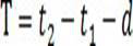
[0098] According to the sending time and the receiving time of the delay test information, the test node extracts the time length from the returned delay test information, and performs network delay calculation to determine the network delay information; wherein,
[0099] The network delay information is determined by the following formula:
[0100]
[0101] in, for the network delay information, for the sending...
Embodiment 3
[0104] In a preferred embodiment, according to the network delay information, judging whether the network of the common node is stable through the test node, and determining a stable node includes:
[0105] Obtaining network delay information of the test node and a single common node;
[0106] According to the network delay information, the test node sorts the network delay information by receiving time to determine a network delay table;
[0107] According to the network delay table, the stability calculation is performed through the test node to obtain a stable value;
[0108] According to the stable value, by comparing with the upper limit of the stable value pre-stored on the test node, determine whether the ordinary node is a stable node; wherein,
[0109] The stable value is determined by the following formula:
[0110]
[0111] in, For the stable value, is the number of data and n≥5, is the data number, for the first network delay information; ;
[011...
PUM
 Abstract
Description
Claims
Application Information
 - R&D
- Intellectual Property
- Life Sciences
- Materials
- Tech Scout
- Unparalleled Data Quality
- Higher Quality Content
- 60% Fewer Hallucinations
Browse by: Latest US Patents, China's latest patents, Technical Efficacy Thesaurus, Application Domain, Technology Topic, Popular Technical Reports.
© 2025 PatSnap. All rights reserved.Legal|Privacy policy|Modern Slavery Act Transparency Statement|Sitemap|About US| Contact US: help@patsnap.com