Carbon fiber composite transmission shaft joint structure

A composite material and joint structure technology, applied in the directions of shafts and bearings, shafts, couplings, etc., can solve the problems of poor pressure resistance, short service life of the main body of the transmission shaft, inconvenient replacement of the main body of the transmission shaft, etc. The effect of connection stability and easy replacement

Pending Publication Date: 2021-02-05
吉林聚鑫碳纤维科技有限公司
View PDF6 Cites 0 Cited by
  • Summary
  • Abstract
  • Description
  • Claims
  • Application Information

AI Technical Summary

Problems solved by technology

[0004] In view of the above situation, in order to overcome the defects of the prior art, the present invention provides a carbon fiber composite material transmission shaft shaft pipe joint structure, which effectively solves the problem of the poor pressure resistance of the transmission shaft main body in the above-mentioned background technology, which leads to the service life of the transmission shaft main body. The problem of short and inconvenient replacement of the drive shaft main body

Method used


Image

  • Carbon fiber composite transmission shaft joint structure
  • Carbon fiber composite transmission shaft joint structure
  • Carbon fiber composite transmission shaft joint structure

Examples


Embodiment 1

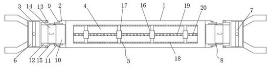
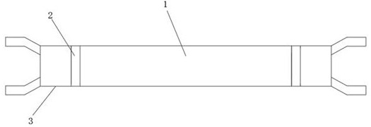
[0022] Embodiment one, by figure 1 , figure 2 and image 3 Given, the present invention comprises a transmission shaft main body 1, two ends of the transmission shaft main body 1 are symmetrically provided with a transmission shaft connecting body 2, both ends of the transmission shaft connecting body 2 are connected with universal joint joints 3, and the inside of the transmission shaft main body 1 A hollow groove 4 is provided. Through the design of the hollow groove 4, the weight of the main body 1 of the transmission shaft is effectively reduced. The inside of the hollow groove 4 is equidistantly provided with reinforcement components 5. Through the connection of the reinforcement components 5 , effectively improving the strength of the transmission shaft main body 1, the interior of the universal joint joint 3 is provided with a cavity groove 2 6, and the interior of the cavity groove 2 6 is provided with a first reinforcing rod 7, and the transmission shaft connecting ...

Embodiment 2

[0023] Embodiment two, on the basis of embodiment one, by figure 1 and figure 2 Given, the joint component 8 includes a joint component 1 and a joint component 2, the joint component 1 is installed on the transmission shaft connecting body 2, and the joint component 2 is mounted on the universal joint 3, so as to facilitate the transmission shaft main body 1 and the universal joint joint 3 connections.

Embodiment 3

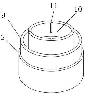
[0024] Embodiment three, on the basis of embodiment two, by figure 1 and image 3 Given, the joint assembly includes a snap ring 9, a joint groove 10 and an insertion groove 11, the snap ring 9 is installed on the transmission shaft connecting body 2, and the middle position of the transmission shaft connecting body 2 is provided with a joint groove 10, An insertion groove 11 is formed around the inner wall of the connecting groove 10, so as to facilitate the connection between the transmission shaft main body 1 and the universal joint 3.


PUM


Abstract

The invention relates to the technical field of automobile tubular shafts and joints, discloses a carbon fiber composite transmission shaft joint structure, and solves the problems that the service life of a transmission shaft body is short and the transmission shaft body is inconvenient to replace due to poor pressure resistance of the transmission shaft body. The carbon fiber composite transmission shaft joint structure comprises a transmission shaft body, wherein transmission shaft connecting bodies are symmetrically arranged at the two ends of the transmission shaft body; universal joint connectors are connected to the two ends of each transmission shaft connecting body; first cavity grooves are formed in the transmission shaft body; reinforcing assemblies are arranged in the first cavity grooves at equal intervals; second cavity grooves are formed in the universal joint connectors; and first reinforcing rods are arranged in the second cavity grooves. By arranging the first cavitygrooves, the weight of the transmission shaft body is effectively reduced, and convenience is brought to use of the transmission shaft body; and through the design of the reinforcing assemblies and reinforcing toothed plates, the strength of the transmission shaft body is effectively improved, and then the compression resistance of the transmission shaft body is improved.

Description

technical field [0001] The invention belongs to the technical field of automobile pipe shafts and joints, in particular to a carbon fiber composite transmission shaft pipe joint structure. Background technique [0002] The transmission shaft is an essential component in the power transmission system of the front-engine rear-drive vehicle. During the power transmission process, the transmission shaft must bear the required torsional load. Bending load, therefore, the stiffness, strength and fatigue life of the transmission shaft have an important impact on the performance of the vehicle. [0003] At present, the transmission shaft of automobiles is welded by steel pipes with a certain diameter and wall thickness and universal joints with equal diameters at both ends. Due to the high density of steel, the mass of the transmission shaft is large, and the pressure resistance of the transmission shaft is poor. At the same time, fuel consumption and emissions The increase will al...

Claims


Application Information

Patent Timeline
Patent Type & Authority Applications(China)
IPC IPC(8): F16C3/02F16D3/16
CPCF16C3/023F16D3/16
Inventor 张丽珠肖宇张革丁芳笑张强
Owner 吉林聚鑫碳纤维科技有限公司
Why Eureka
Try Eureka