Elevator entrance threshold stone structure capable of preventing impact damage and convenient to construct and maintain

A technology of impact damage and threshold stone, which is applied in the field of architectural decoration and decoration, can solve the problems of inconvenient maintenance and operation of threshold stone, increased fragmentation of threshold stone, insufficient mortar filling at the bottom of threshold stone, etc., so as to reduce the probability of cracking in the hollow area and reduce the Probability of being damaged by impact, eliminating the effect of threshold stone being broken by impact

Inactive Publication Date: 2021-02-05
POWERCHINA HUADONG ENG COPORATION LTD
View PDF7 Cites 0 Cited by
  • Summary
  • Abstract
  • Description
  • Claims
  • Application Information

AI Technical Summary

Problems solved by technology

[0003] The shortcomings of the threshold stone constructed in the traditional structure form in the later use and maintenance are as follows: First, in the operation stage, the probability of the threshold stone being broken after being impacted by external force increases, which increases the maintenance cost in the later period
If the threshold stone is not replaced, the tortoise cracks will develop from cracks at the edge of the threshold stone to penetrating cracks, which will seriously affect the aesthetics of the building; if the threshold stone is replaced, the maintenance cost will increase
[0004] Second, during the maintenance process, the threshold stone maintenance operation is inconvenient
When adopting the existing threshold stone structure, electric or pneumatic demolition equipment or manual chiseling are required for replacement
During the demolition process, since the distance between the damaged threshold stone and the elevator door, elevator sill, elevator exit door casing, and adjacent floor tiles is within 2mm, and the operating space is limited, mechanical operations are likely to cause damage to surrounding materials and further expand losses. , it is more difficult to remove
At the same time, when reinstalling the new threshold stone coated with cement mortar at the bottom into the original groove, the gap between the original groove and the surrounding area is usually only 1-2 mm, and the installation space is insufficient. It takes a long time to fix it in the original installation groove. Due to the fluidity of the cement mortar, the mortar at the bottom of the threshold stone will continue to fall off during the installation process, resulting in insufficient filling of the mortar at the bottom of the threshold stone, and there will still be thresholds for re-paving The mortar on the edge of the lower part of the stone is not fully filled, hollow, or it is not tightly bonded to the threshold stone, which lays hidden dangers for the threshold stone to be damaged again after being impacted by a trolley transporting heavy objects
[0005] Third, during the maintenance process, it takes a long time to adversely affect the building facilities, adjacent elevator facilities, and the normal use of the building
During maintenance, it takes a long time to remove the original broken threshold stone and the lower bonding layer; at the same time, it takes a long time to wait for the lower bonding mortar to harden completely after the threshold stone paving is completed, so it is necessary to stop the corresponding elevator for a long time operation, which will affect the normal use of elevators and buildings for a long time

Method used


Image

  • Elevator entrance threshold stone structure capable of preventing impact damage and convenient to construct and maintain
  • Elevator entrance threshold stone structure capable of preventing impact damage and convenient to construct and maintain

Examples


Embodiment Construction

[0022] The present invention will be further described below in conjunction with the accompanying drawings and embodiments, but not as a basis for limiting the present invention.

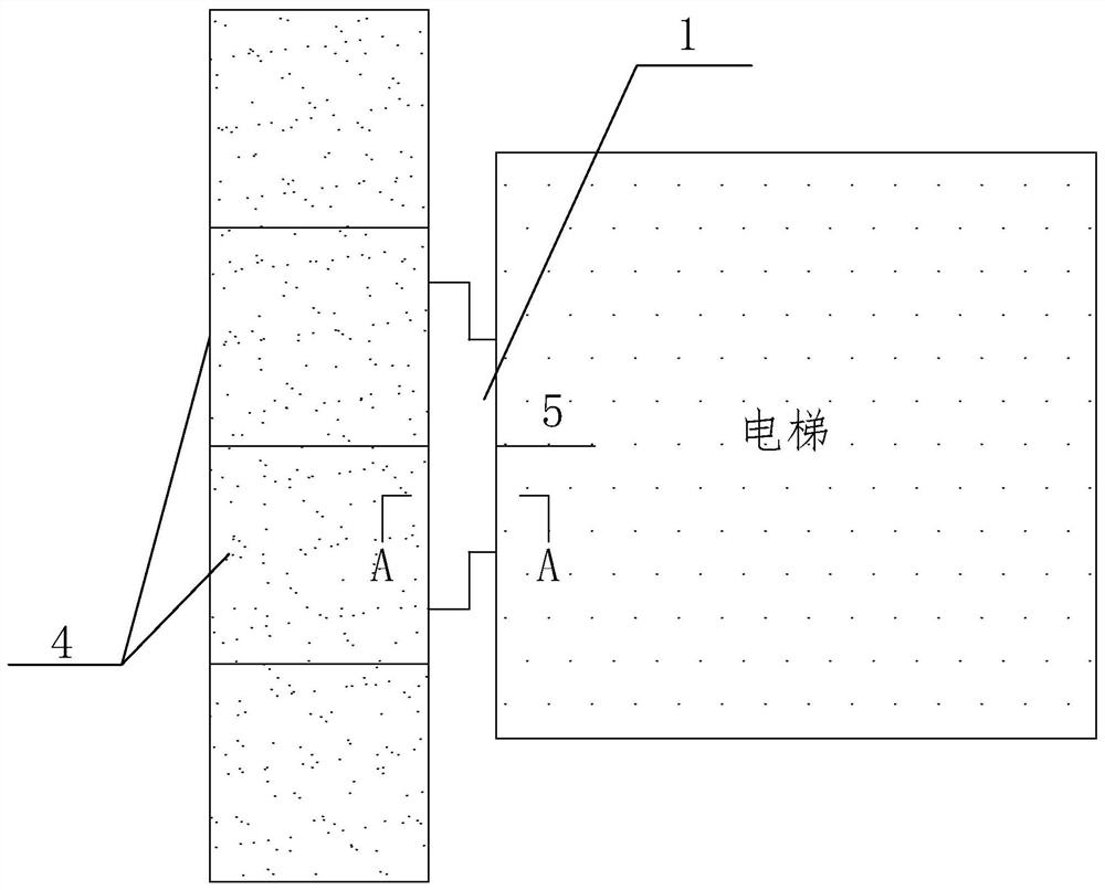
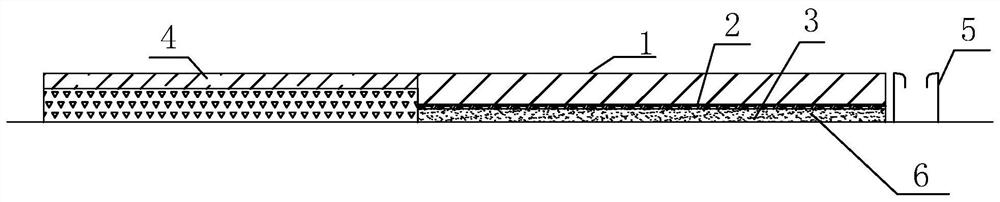
[0023] like Figure 1-Figure 2 As shown, a kind of anti-impact damage provided by the present invention and convenient for construction and maintenance of the threshold stone structure of the elevator entrance includes the main leveling layer 6 of the building ground, the elevator door sill 5, the floor tile paving area 4 in the building and the threshold stone 1. The threshold stone 1 is laid on the main leveling layer 6 of the building ground between the floor tile paving area 4 and the elevator door sill 5 in the building. A non-rigid support structure is set between the main leveling layer 6 of the building ground and the threshold stone 1, which plays the role of non-rigid support and replaces the traditional threshold stone paving cement mortar bonding layer, that is, the threshold stone rigid...


PUM


Abstract

The invention provides an elevator entrance threshold stone structure capable of preventing impact damage and convenient to construct and maintain. The elevator entrance threshold stone structure comprises a building ground main leveling layer, an elevator door sill, an in-building floor tile paving area and threshold stone. The threshold stone is paved on the position, between the in-building floor tile paving area and the elevator door sill, of the building ground main leveling layer. The height of the in-building floor tile paving area is consistent with or approximately consistent with that of the elevator door sill, and a non-rigid bearing structure is arranged between the building ground main leveling layer and the threshold stone. The non-rigid bearing structure comprises a graded sand secondary leveling and auxiliary buffer layer arranged above the building ground main leveling layer, and a rubber plate main buffer layer is arranged above the graded sand secondary leveling andauxiliary buffer layer. According to the elevator entrance threshold stone structure capable of preventing impact damage and convenient to construct and maintain, non-rigid supporting is provided forthe threshold stone, meanwhile, the elevation and flatness of the threshold stone can further be adjusted, so that the top face of the threshold stone is consistent with the top face of the elevator door sill in elevation, the impact damage probability is reduced, and meanwhile, the overall attractiveness of building decoration is further improved.

Description

technical field [0001] The invention relates to the technical field of building decoration and decoration, in particular to an elevator door sill stone structure that prevents impact damage and is convenient for construction and maintenance. Background technique [0002] Arranging threshold stones for decoration between the elevator sill and the floor tiles in the building is a common decoration method in architectural decoration engineering. The traditional elevator door threshold stone structure is set in order from the level of the undecorated ground in the house. Layer, threshold stone paving cement mortar adhesive layer, threshold stone, a total of three-layer structure, wherein the threshold stone paving cement mortar adhesive layer is the threshold stone rigid supporting layer. Under the condition of the traditional threshold stone structure, the common main construction process is: the first step is to carry out the main screed construction; the second step is to pla...

Claims


Application Information

Patent Timeline
Patent Type & Authority Applications(China)
IPC IPC(8): E06B1/70E04F15/02B66B13/30
CPCE06B1/70E04F15/02B66B13/30E06B2001/707
Inventor 李俊林靓靓殷朝华杨浩锋芦超朱爽李源吉乔伟陶如钧张革强
Owner POWERCHINA HUADONG ENG COPORATION LTD
Why Eureka
Try Eureka