A fully assembled modular expansion joint

An expansion joint, modular technology, applied in the erection/assembly of bridges, buildings, bridge construction, etc., can solve the problems of large pouring volume, limited working space, prolonged construction cycle time, etc. And the effect of solid foundation and reduction of installation defects

Active Publication Date: 2022-03-04
ANHUI TRANSPORT CONSULTING & DESIGN INST +1
View PDF0 Cites 0 Cited by
  • Summary
  • Abstract
  • Description
  • Claims
  • Application Information

AI Technical Summary

Problems solved by technology

[0004] (1) Long construction time: It takes a long time for the cast-in-place concrete at the base of the telescopic device to reach the design strength, and the on-site procedures are complicated, resulting in an extended construction period;
[0005] (2) Difficulty in construction: construction is too cumbersome, and it is difficult to achieve complete modularization and standardization of expansion device components. On-site cutting, cleaning and welding require a lot of manpower and equipment, which is difficult to adapt to the current bridge assembly;
[0006] (3) The quality of concrete pouring is difficult to guarantee: the traditional telescopic device has a large amount of concrete poured on site. Due to the limited working space, the quality of concrete pouring is difficult to guarantee. Under the repeated load of the vehicle, the concrete at the base of the telescopic device is prone to voids, holes, and crushing and other diseases, which will lead to damage to the seam body and shorten the life span;
[0007] (4) The durability of the telescopic device is poor and the disease occurs frequently: due to the difficulty in guaranteeing the quality of concrete pouring and the lack of effective measures to ensure the top surface of the structure of the telescopic device is flat, in the case of initial defects in the installation, the durability of the telescopic device is poor, the disease occurs frequently, and the maintenance is frequent

Method used


Image

  • A fully assembled modular expansion joint
  • A fully assembled modular expansion joint
  • A fully assembled modular expansion joint

Examples


Embodiment 1

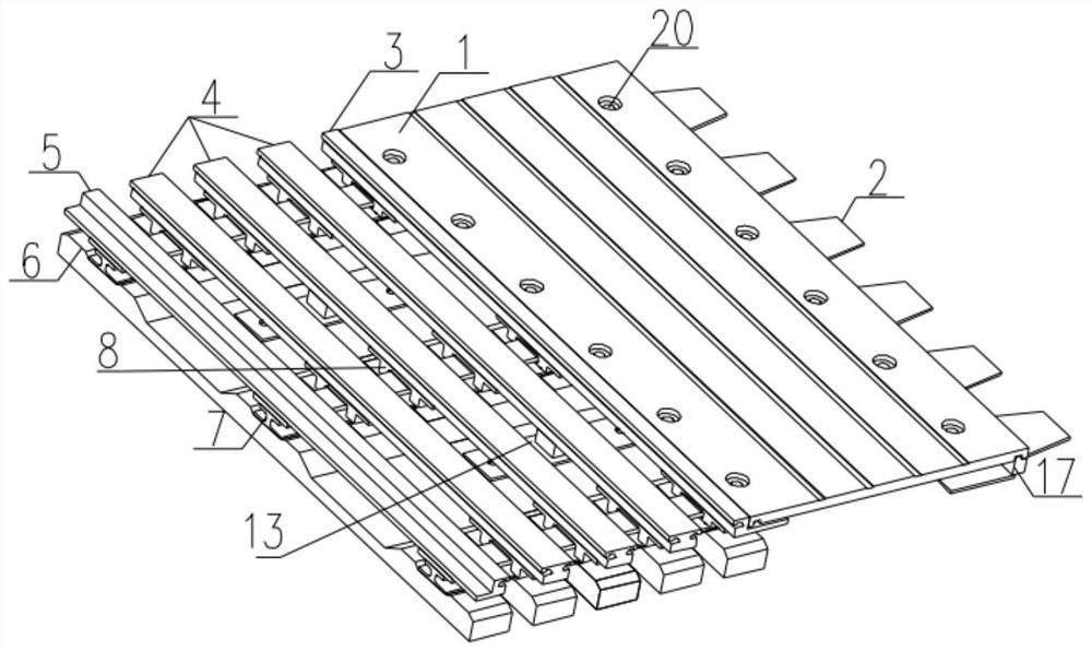
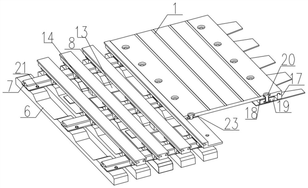
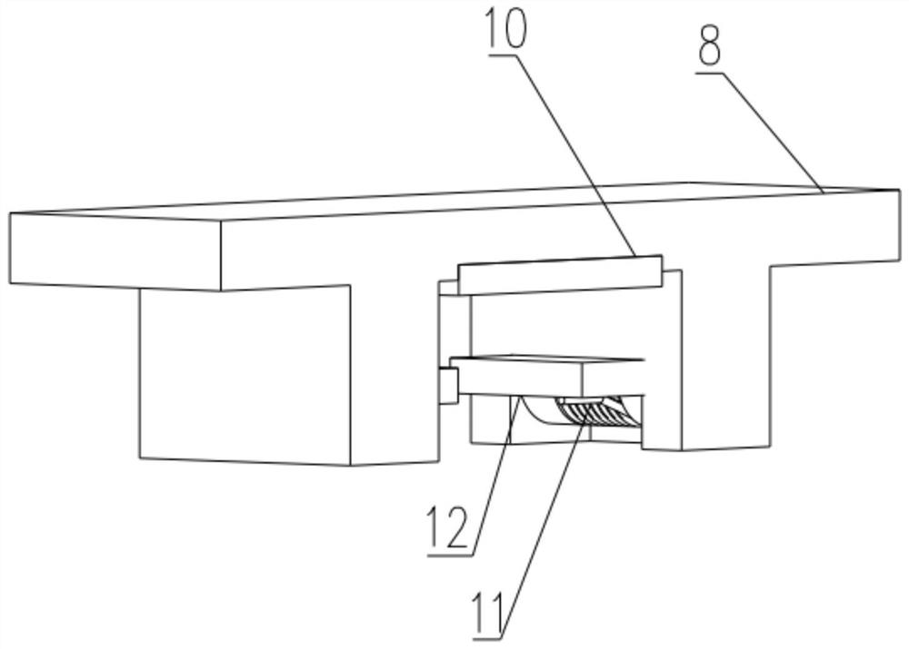
[0038] Embodiment 1, as shown in the figure, spanning board 1, fixed bottom plate 2, movable side beam 3, movable middle beam 4, fixed side beam 5, prefabricated sleeper 6, rail 7, slider 8, wear-resistant slide plate 10, torsion spring 11 , Movable slide plate 12, connecting plate 13, fixed connecting block 14, rubber spring 15, inserting rod 16, baffle plate 17, first elastic rubber bearing 18, bearing block 19, anti-loosening bolt 20, bolt 21, second Elastic rubber bearing 22, leveling bolt 23.

[0039] Fully-assembled modular bridge expansion device, including expansion components, spanning components, displacement control components, sliders and support components, the expansion components are limited to the support components set on the beam body, and one end of the spanning plate passes through the anti-loosening bolts It is fixed on the elastic support of the bottom plate at the fixed end, and the other end is fixed on the elastic support of the movable side beam throu...


PUM


Abstract

The invention provides a fully-assembled modular expansion joint, which relates to the field of expansion devices for bridge girders, and includes a telescopic assembly, a joint-spanning assembly, a displacement control assembly, a slider and a supporting assembly. All components of the expansion joint adopt modular design to realize fully assembled installation. The expansion component and support component of the expansion device are integrally set on the beam body to work. The support component adopts a combination of prefabricated sleepers and rails. The method is simple and clear, the installation of the telescopic device is simple and fast, and the later inspection, maintenance and replacement of the structure are more convenient, which is consistent with the current bridge assembly concept, and the overall function can be realized safely, with long-term stability and long service life.

Description

technical field [0001] The invention relates to the field of telescopic devices for bridge girders, and is especially suitable for large bridges or extra-large bridges with a telescopic amount of more than 160mm, and in particular to a fully assembled modularized bridge telescopic device. Background technique [0002] With the continuous development of my country's economy, the scale of infrastructure construction such as bridges continues to expand, and the amount of bridge expansion devices is increasing, and the scope of use is becoming wider and wider. People have higher and higher requirements for driving comfort, safety and reliability, and the use performance and safety performance of expansion joint devices have been highly valued. Expansion joints are one of the key structures on bridge girders. The main types include rubber expansion joints, steel expansion joints, modular steel expansion joints, comb-tooth plate expansion joints, and seamless expansion joints. ...

Claims


Application Information

Patent Timeline
Patent Type & Authority Patents(China)
IPC IPC(8): E01D19/06E01D21/00
CPCE01D19/065E01D21/00
Inventor 杨大海汪志甜吴平平陈修和单文胜谢玉萌刘婉玥周云张龙
Owner ANHUI TRANSPORT CONSULTING & DESIGN INST
Why Eureka
Try Eureka