Prefabricated reinforced concrete column and composition board joint and construction process
A technology of reinforced concrete columns and composite slabs, which is applied in the direction of columns, pier columns, pillars, etc., can solve the problems of weak seismic performance of joints, poor stiffness against lateral force, and poor shear resistance, so as to achieve good economic benefits and ensure force bearing Performance, weight reduction effect
- Summary
- Abstract
- Description
- Claims
- Application Information
AI Technical Summary
Problems solved by technology
Method used
Image
Examples
Embodiment 1
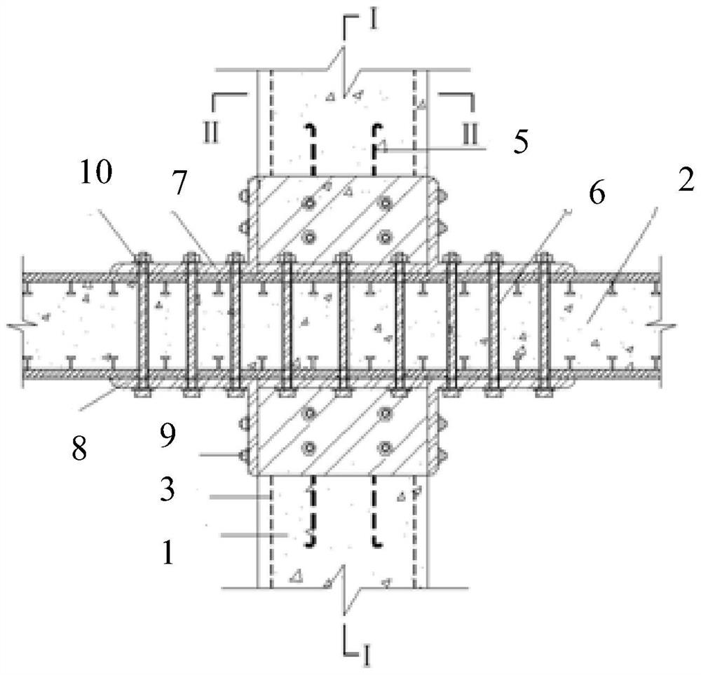
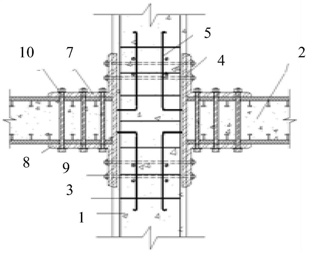
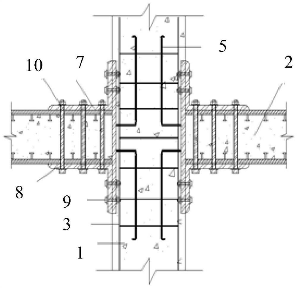
[0032] Embodiment 1: In the embodiment of the first aspect of the present invention, such as Figure 1 to Figure 10 As shown, the present invention provides a prefabricated reinforced concrete column 1 and a composite slab joint, including a reinforced concrete column 1, a steel plate sandwich concrete composite slab 2 and a connecting assembly, and the connecting assembly is the same as the reinforced concrete column 1 and the steel plate sandwich concrete composite slab 2 Connection, the steel plate sandwich concrete composite panel 2 is provided with a first connection hole, the reinforced concrete column 1 passes through the first connection hole, and is connected with the steel plate sandwich concrete composite panel 2 through a connection assembly.
[0033] In this embodiment, the reinforced concrete column 1 and the composite slab node include a reinforced concrete column 1, a steel plate sandwich concrete composite slab 2 and a connecting assembly, and the connecting as...
Embodiment 2
[0034] Embodiment 2: as Figure 1 to Figure 7 As shown, the reinforced concrete column 1 includes a steel bar skeleton 3, a circumferential steel plate sleeve 4 and a plurality of second connection holes, the inner side of the circumferential steel plate sleeve 4 is welded with an anchoring steel bar 5, and 4 sets of circumferential steel plate sleeves Set in the middle of the steel frame 3, the vertical section of the anchor bar 5 is welded on the steel frame 3, a plurality of second connecting holes pass through the circumferential steel plate sleeve 4, and are set on the reinforced concrete column 1, and the template is used at the steel frame 3 Concrete is integrally poured into the steel plate sleeve 4 in the ring; the steel plate sandwich concrete composite plate 2 includes an upper steel plate, a lower steel plate, concrete poured between the upper steel plate and the lower steel plate, and a plurality of third connecting holes 6, the upper steel plate and the lower stee...
Embodiment 3
[0036] Embodiment 3: as Figure 8 to Figure 10 As shown, the connecting assembly includes a supporting plate 11 and a plurality of third bolts 13, the supporting plate 11 is arranged on the reinforced concrete column 1, and is formed by pouring concrete from the supporting plate steel bar 12, and the steel pipe concrete column is formed by pouring concrete from the reinforced skeleton 3 The pallet reinforcement 12 is connected with the reinforcement frame 3, the reinforcement frame 3 and the pallet reinforcement 12 are all poured with concrete, the third bolt 13 is arranged on the pallet 11, and the steel plate sandwich concrete composite plate 2 includes an upper steel plate, a lower The concrete poured between the steel plate, the upper steel plate and the lower steel plate and a plurality of sixth connecting holes, the upper steel plate and the lower steel plate are arranged in parallel, the first connecting hole is pierced on the upper steel plate and the lower steel plate,...
PUM
 Abstract
Description
Claims
Application Information
 - R&D
- Intellectual Property
- Life Sciences
- Materials
- Tech Scout
- Unparalleled Data Quality
- Higher Quality Content
- 60% Fewer Hallucinations
Browse by: Latest US Patents, China's latest patents, Technical Efficacy Thesaurus, Application Domain, Technology Topic, Popular Technical Reports.
© 2025 PatSnap. All rights reserved.Legal|Privacy policy|Modern Slavery Act Transparency Statement|Sitemap|About US| Contact US: help@patsnap.com


