Wire winding device for power transmission and distribution engineering construction

A winding device and engineering construction technology, applied in the direction of transportation and packaging, delivery of filamentous materials, thin material processing, etc., can solve the problems of inconvenient removal and inability to control the winding amount of wires well, so as to achieve the convenience of equipment use , the effect of compact wire winding

Inactive Publication Date: 2021-02-05
黄永红
View PDF1 Cites 0 Cited by
  • Summary
  • Abstract
  • Description
  • Claims
  • Application Information

AI Technical Summary

Problems solved by technology

[0004] In order to overcome the shortcomings of the current wire winding method that it is inconvenient to take out and the amount of wire winding cannot be well controlled, the technical problem to be solved is: to provide a power transmission that can easily take out the wound wire and accurately control the amount of wire winding. Wire winding device for power distribution engineering construction

Method used


Image

  • Wire winding device for power transmission and distribution engineering construction
  • Wire winding device for power transmission and distribution engineering construction
  • Wire winding device for power transmission and distribution engineering construction

Examples


Embodiment 1

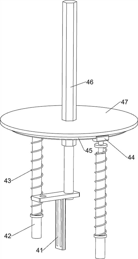
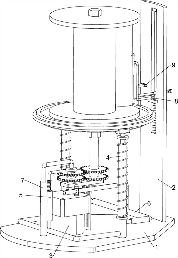
[0027]A wire winding device for power transmission and distribution engineering construction, such asFigure 1-Figure 6As shown, it includes a bottom plate 1, a supporting plate 2, a geared motor 3, a lifting and placing component 4, a control component 5, an air intake component 6 and a bleeder component 7. The top left side of the bottom plate 1 is fixed with a geared motor 3 through bolts. 1 The top right side is fixed with a supporting plate 2 through bolts, the bottom plate 1 is equipped with a lifting placement assembly 4 in the middle of the top, a control module 5 is installed at the top left of the bottom plate 1, and the lifting placement assembly 4 is equipped with an air intake assembly 6 on the right side, which is placed in a lifting position On the left side of the assembly 4 is installed a deflation assembly 7 which is controlled by a lifting method.

[0028]When it is necessary to use the device to wind wires, first place the wire-wound barrel on the lifting and placing...

Embodiment 2

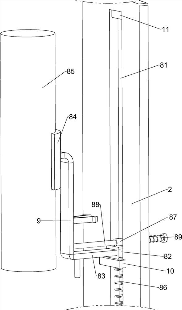
[0038]On the basis of Example 1, such asfigure 1 ,Figure 7 withFigure 8 As shown, it also includes a compaction assembly 8. The upper part of the support plate 2 is equipped with a compaction assembly 8. The compaction assembly 8 includes a square hollow sleeve 82, a sliding plate 83, an arc plate 84, a cylinder 85, a fourth spring 86, The circular sliding sleeve 87, the sliding rod 88 and the fifth spring 89 are provided with a sliding groove 81 on the upper part of the support plate 2, a square hollow sleeve 82 is slidably arranged in the sliding groove 81, and a sliding plate 83 is slidably arranged in the square hollow sleeve 82. An arc plate 84 is welded on the upper left side of the sliding plate 83. The arc plate 84 is provided with a cylinder 85 on the left side. A fourth spring 86 is connected between the bottom of the square hollow sleeve 82 and the support plate 2, and the top of the square hollow sleeve 82 passes A circular sliding sleeve 87 is fixedly connected to the s...


PUM


Abstract

The invention relates to a winding device, in particular to a wire winding device for power transmission and distribution engineering construction. According to the wire winding device for power transmission and distribution engineering construction, a wound wire can be conveniently taken out, and the wire winding amount can be accurately controlled. The wire winding device for power transmissionand distribution engineering construction comprises a bottom plate, a support plate arranged on the bottom plate, a gear motor arranged on the bottom plate, a lifting placement component arranged on the bottom plate, a control component arranged on the bottom plate, an air inlet component arranged on the lifting placement component, and a deflation component arranged on the lifting placement component. Through cooperation of the lifting placement component, the control component, the air inlet component and the deflation component, uniform winding of the wire through up-down movement is achieved, and the requirement for wire winding is well met; and by means of a compacting component, a cylinder can compact the wound wire in the whole process, and the wire can be wound more compactly.

Description

Technical field[0001]The invention relates to a winding device, in particular to a wire winding device for power transmission and distribution engineering construction.Background technique[0002]Wire refers to a product with a small number of cores, a small product diameter, and a simple structure. It is used as a material for power, communication and related transmission purposes. When the wire is installed, it is rolled into a ball. During the installation process, the rolled wire It's easy to mess up, and it's very inconvenient.[0003]The patent application publication number CN108217302A discloses a wire winding device for power transmission and distribution engineering construction, in particular, it relates to a wire winding device for power transmission and distribution engineering construction. The technical problem to be solved is to provide a wire winding device for power transmission and distribution engineering construction with high winding efficiency, compactness, time a...

Claims


Application Information

Patent Timeline
IPC IPC(8): B65H54/44B65H54/28B65H59/00B65H63/00
CPCB65H54/2803B65H54/283B65H54/44B65H59/00B65H63/00B65H2701/34
Inventor 黄永红
Owner 黄永红
Why Eureka
Try Eureka