
Lens injection molding automation equipment and control method thereof

A technology of automatic equipment and control method, which is applied to other household appliances, optical components, household appliances, etc., and can solve the problems that visual detection methods are difficult to meet the requirements, the space for the connection part of the nozzle is small, and the lens has a curvature.

Pending Publication Date: 2021-02-05
吴国强
View PDF0 Cites 0 Cited by
  • Summary
  • Abstract
  • Description
  • Claims
  • Application Information

AI Technical Summary

Problems solved by technology

In order to realize automatic nozzle cutting, it is impossible to use the same set of molds for nozzle punching
Moreover, the space of the connection part of the nozzle is very small, and it cannot be realized with air shears.
[0007] It is necessary to carry out quality inspection for each lens. The transparency of the lens is high, and the accuracy of the defect detection is also high. However, the lens has a curvature, and the commonly used visual inspection methods are difficult to meet the requirements.
[0008] At present, these aspects of lens production still rely heavily on manual labor, and there is no set of related equipment in the market that can automate the above-mentioned lens process.

Method used


Image

  • Lens injection molding automation equipment and control method thereof
  • Lens injection molding automation equipment and control method thereof
  • Lens injection molding automation equipment and control method thereof

Examples


Embodiment Construction

[0051] In order to make the object, technical solution and advantages of the present invention more clear, the present invention will be further described in detail below in conjunction with the examples. It should be understood that the specific embodiments described here are only used to explain the present invention, not to limit the present invention.

[0052] Aiming at the problems existing in the prior art, the present invention provides a lens injection molding automation equipment and its control method. The present invention will be described in detail below with reference to the accompanying drawings.

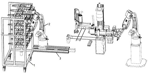
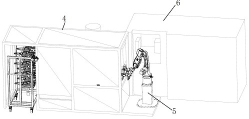
[0053] Such as figure 1 and figure 2 As shown, the frame body 4 and the injection molding robot 5 in the lens injection molding automation equipment provided by the embodiment of the present invention are arranged on the side of the injection molding machine 6, and the inside of the frame body is provided with a water cutting mechanism, a dust removal module, a dete...


PUM


Abstract

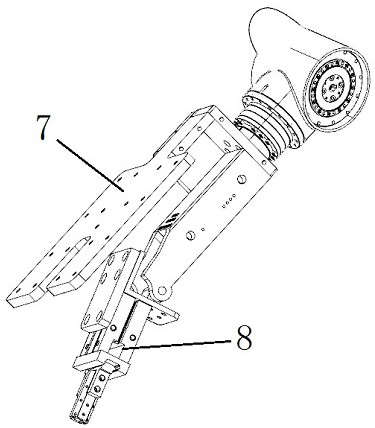
The invention belongs to the technical field of lens injection molding, and discloses lens injection molding automation equipment and a control method thereof. A frame body is provided with a water gap cutting mechanism, a quality inspection mechanism, a lens inserting robot, a frame taking mechanism and a frame overturning and positioning mechanism. An injection molding robot is a six-axis robot,and a six-axis robot tool is provided with an overturning device and a pneumatic clamping jaw assembly. The water gap cutting mechanism comprises a servo rotating assembly and a hot punching assembly. The quality inspection mechanism comprises an optical system and an industrial personal computer. The frame taking mechanism comprises a frame taking robot, a frame taking tool and a feeding cart. The frame overturning and positioning mechanism comprises two sets of rotating and positioning devices. The lens injection molding automation equipment is matched with a single injection molding machine, and the functions of lens taking, automatic film taking, film pasting, automatic water gap cutting, automatic quality inspection, automatic lens inserting, automatic frame feeding and discharging and the like of the injection molding machine are achieved; and the lens injection molding automation equipment is matched with vertical and horizontal injection molding machines of all types and tonnages and can be matched with the injection molding machines, and lenses are rapidly, accurately and automatically taken out of the injection molding machines.

Description

technical field [0001] The invention belongs to the technical field of lens injection molding, and in particular relates to an automatic equipment for lens injection molding and a control method thereof. Background technique [0002] At present: In the optical field, we usually use injection molded lenses, which are molded by plastic particles through an injection molding machine through a mold. Usually a lens mold contains multiple mold cavities, and one injection can mold multiple lenses. Branches and nozzles are connected between the lenses. After the injection molding is completed, the connected lenses need to be individually cut from the nozzle for subsequent process production. And every lens needs to be inspected to ensure that the lens is complete and flawless. The inspected lenses need to be uniformly hung on the corresponding jigs for subsequent batch processing. The existing lens injection molding equipment has a low degree of automation and mainly relies on m...

Claims


Application Information

Patent Timeline
Patent Type & Authority Applications(China)
IPC IPC(8): B29C45/17B29C45/38B29C45/76B07C5/00B07C5/02B07C5/36B07C5/38B29L11/00
CPCB29C45/1769B29C45/382B29C45/76B07C5/00B07C5/02B07C5/362B07C5/38B29L2011/0016B07C2501/0063
Inventor 吴国强
Owner 吴国强
Learn More